539
Memory Allocations Section 9-9
9-9-2 DM Area Allocation
The memory allocation about system setup is shown as the following diagram.
These data will be allocated to the DM area of PLC. The beginning DM chan-
nel n is calculated by the following equation.
Note 1. DM area from n to n+154 can only display all of the settings stared in the
unit. Modification in this area is invalid to the CP1W-CIF41 Ethernet Option
Board.
2. DM area n+155 and n+156 will display the IP address used by the CP1W-
CIF41 when the power is turned ON.
3.
When the IP address is illegal, such as using CLASS D, CLASS E IP
address, the values in words n+3 and n+155 will be different, and the
CP1W-CIF41 will temporarily use the default IP address (192.168.250.1).
Use this IP address to modify the IP address settings through Web
browser.
n = DM32000 + 300×(0xFD - Unit Address)
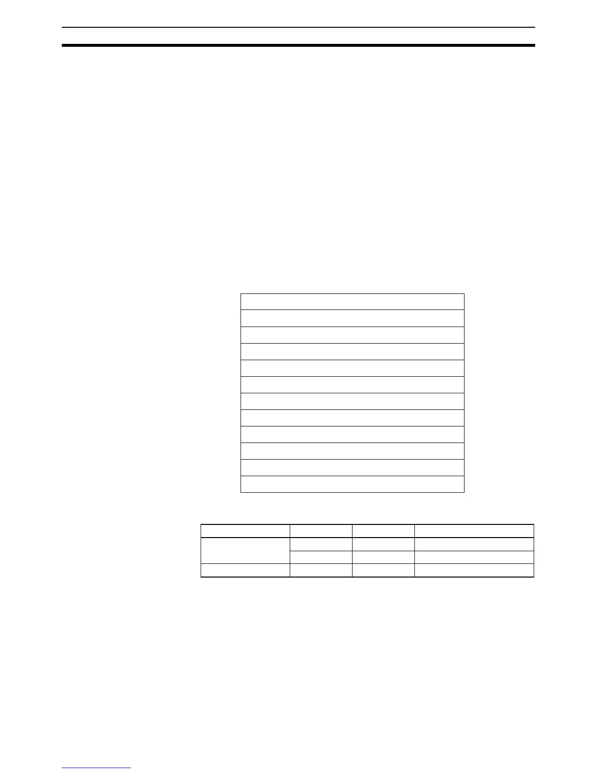
The following table describes the unit address for each option port.
Offset D15 D0
n Mode setting (2 bytes)
n+1 FINS/TCP port number (2 bytes)
n+2 FINS/UDP port number (2 bytes)
n+3 IP address (4 bytes)
n+5 Subnet mask (4 bytes)
n+7 Reserved (2 bytes)
n+8 IP address table (194 bytes)
n+105 IP router table (66 bytes)
n+138 FINS/TCP connection setup (22 bytes)
n+149 HTTP server setup (10 bytes)
n+154 FINS node address (2 bytes)
n+155 Using IP Address Display/Setting Area (4 bytes)
Option Port No. I/O Capacity Unit Address Range of Status Area
Option port 1 14/20 0xFC DM32300 to DM32456
30/40/60 0xFD DM32000 to DM32156
Option port 2 30/40/60 0xFC DM32300 to DM32456