48
Specifications Section 2-2
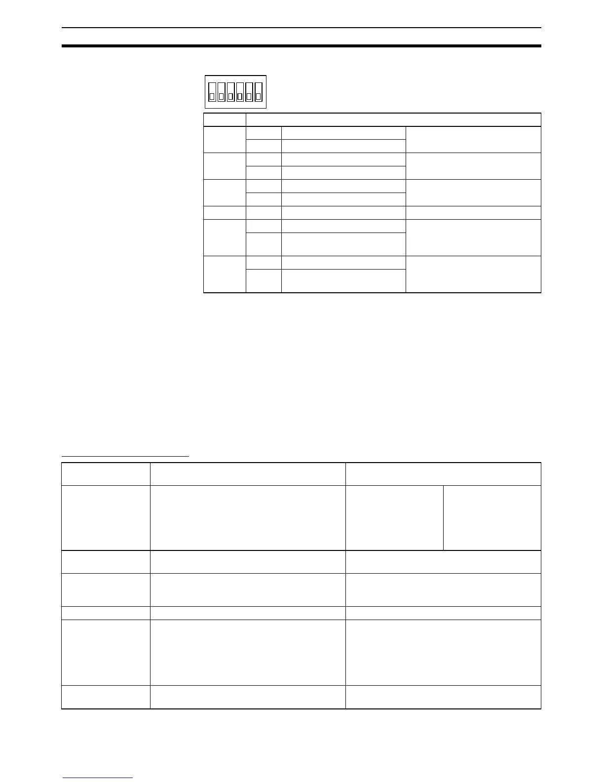
DIP Switch for Operation Settings
Note (1) Set both pins 2 and 3 to either ON (2-wire) or OFF (4-wire).
(2) To disable the echo-back function, set pin 5 to ON (RS control enabled).
(3) When connecting to a device on the N side in a 1: N connection with the
4-wire method, set pin 6 to ON (RS control enabled).
Also, when connecting by the 2-wire method, set pin 6 to ON (RS control
enabled).
2-2 Specifications
2-2-1 CP1H CPU Units
General Specifications
Pin Settings
1 ON ON (both ends) Terminating resistance selection
OFF OFF
2 ON 2-wire 2-wire or 4-wire selection (See
note 1.)
OFF 4-wire
3 ON 2-wire 2-wire or 4-wire selection (See
note 1.)
OFF 4-wire
4 --- --- Not used.
5 ON RS control enabled RS control selection for RD (See
note 2.)
OFF RS control disabled (Data
always received.)
6 ON RS control enabled RS control selection for SD (See
note 3.)
OFF RS control disabled (Data
always sent.)
O
N
1
2
3
4
5
6
Power supply
classification
AC power supply DC power supply
Model numbers • XA CPU Units
CP1H-XA40DR-A
• X CPU Units
CP1H-X40DR-A
• XA CPU Units
CP1H-XA40DT-D
CP1H-XA40DT1-D
• X CPU Units
CP1H-X40DT-D
CP1H-X40DT1-D
• Y CPU Units
CP1H-Y20DT-D
Power supply 100 to 240 VAC
50/60 Hz
24 VDC
Operating voltage
range
85 to 264 VAC 20.4 to 26.4 VDC
(with 4 or more Expansion Units and Expansion
I/O Units: 21.6 to 26.4 VDC)
Power consumption 100 VA max. 50 W max.
Inrush current
(See note.)
100 to 120 VAC inputs:
20 A max.(for cold start at room temperature.)
8 ms max.
200 to 240 VAC inputs:
40 A max.(for cold start at room temperature.)
8 ms max.
30 A max.(for cold start)
20 ms max.
External power sup-
ply
300 mA at 24 VDC None