232
Pulse Outputs Section 5-3
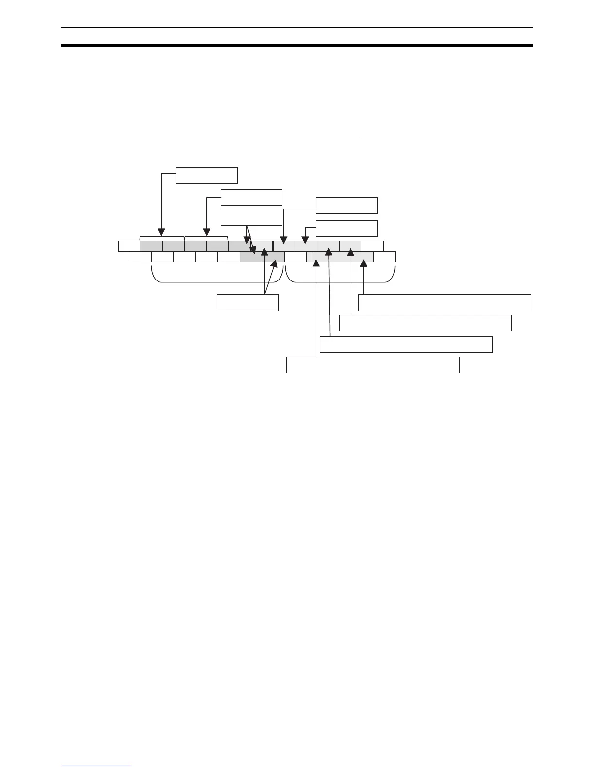
5-3-3 Pulse Output Terminal Allocations
The following diagrams show the terminals that can be used for pulse outputs
in each CPU Unit.
X/XA CPU Units
■ Output Terminal Block Arrangement
NC 00 01 02 03 04 06 00 01 03 04 06
NC
COM
COM COM
COM
05 07
COM
02 05 07
Lower Terminal Block
(Example: Transistor Outputs)
CIO 100
Pulse output 0
COM
Pulse output 1
Pulse output 3
Pulse output 2
PWM output 0
PWM output 1
Origin search 3 (Error counter reset output)
Origin search 2 (Error counter reset output)
Origin search 1 (Error counter reset output)
Origin search 0 (Error counter reset output)
CIO 101