231
Pulse Outputs Section 5-3
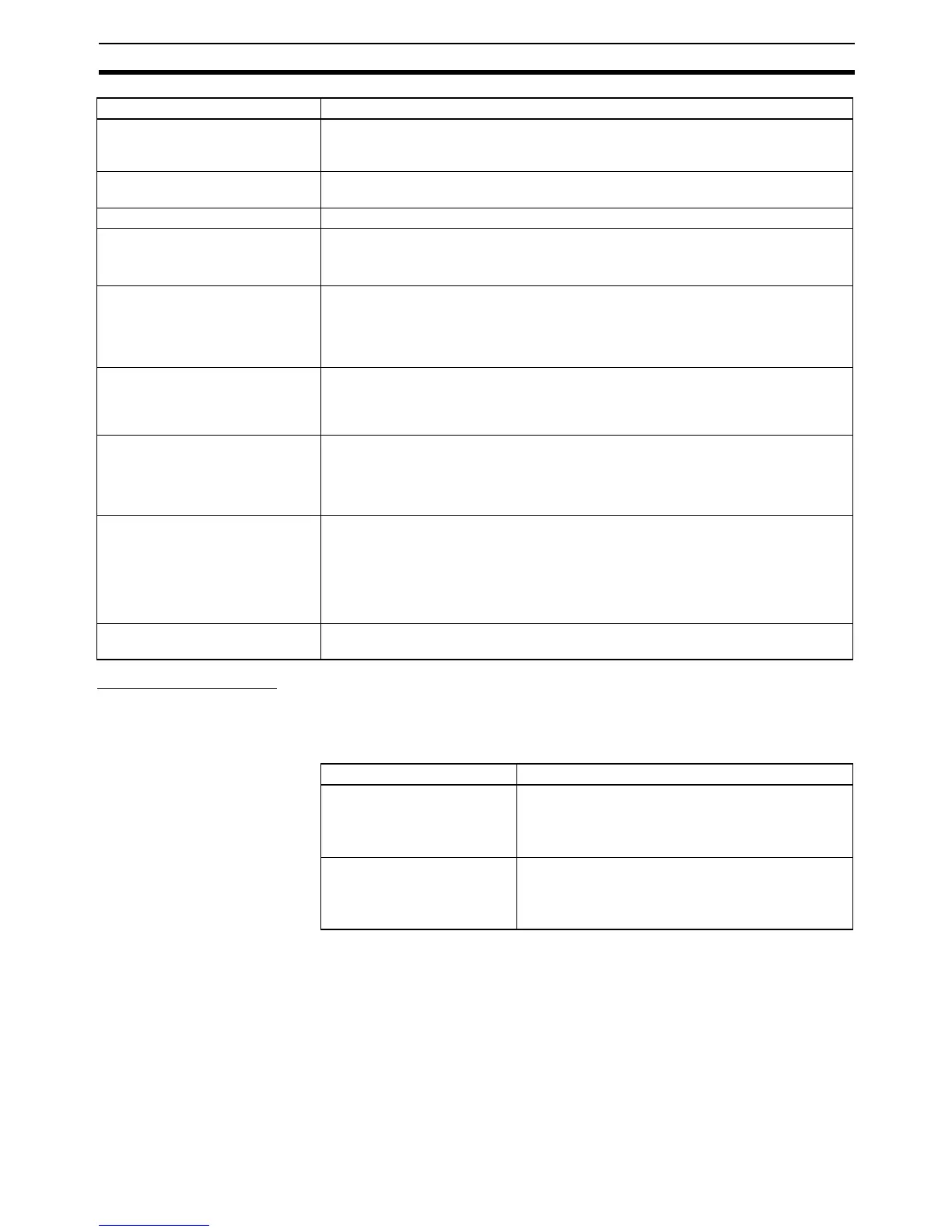
Pulse Output Modes
There are two pulse output modes. In independent mode the number of out-
put pulses is specified and in continuous mode the number of output pulses is
not specified.
Frequency acceleration and decel-
eration rates
Set in 1 Hz units for acceleration/deceleration rates from 1 Hz to 65,635 Hz (every 4
ms). The acceleration and deceleration rates can be set independently only with
PLS2(887).
Changing SVs during instruction
execution
The target frequency, acceleration/deceleration rate, and target position can be
changed.
Duty factor Fixed at 50%
Pulse output method CW/CCW inputs or Pulse + direction inputs
The method is selected with an instruction operand. The same method must be used
for pulse outputs 0 and 1.
Number of output pulses Relative coordinates: 00000000 to 7FFFFFFF hex
(Each direction accelerating or decelerating: 2,147,483,647)
Absolute coordinates: 80000000 to 7FFFFFFF hex
(−2147483648 to 2147483647)
Pulse output PV's relative/absolute
coordinate specification
Absolute coordinates are specified automatically when the origin location has been
determined by setting the pulse output PV with INI(880) or performing an origin
search with ORG(889). Relative coordinates are used when the origin location is
undetermined.
Relative pulse specification/
Absolute pulse specification
The pulse type can be specified with an operand in PULS(886) or PLS2(887).
Note The absolute pulse specification can be used when absolute coordinates are specified for
the pulse output PV, i.e. the origin location has been determined.
The absolute pulse specification cannot be used when relative coordinates are specified,
i.e. the origin location is undetermined. An instruction error will occur.
Pulse output PV's storage location The following Auxiliary Area words contain the pulse output PVs:
Pulse output 0: A277 (leftmost 4 digits) and A276 (rightmost 4 digits)
Pulse output 1: A279 (leftmost 4 digits) and A278 (rightmost 4 digits)
Pulse output 2: A323 (leftmost 4 digits) and A322 (rightmost 4 digits)
Pulse output 3: A325 (leftmost 4 digits) and A324 (rightmost 4 digits)
The PVs are refreshed during regular I/O refreshing.
Acceleration/deceleration curve
specification
Trapezoidal or S-curve acceleration/deceleration
Item Specifications
Mode Description
Independent mode This mode is used for positioning.
Operation stops automatically when the preset num-
ber of pulses has been output. It is also possible to
stop the pulse output early with INI(880).
Continuous mode This mode is used for speed control.
The pulse output will continue until it is stopped by
executing another instruction or switching the PLC to
PROGRAM mode.