727
PLC Setup Appendix G
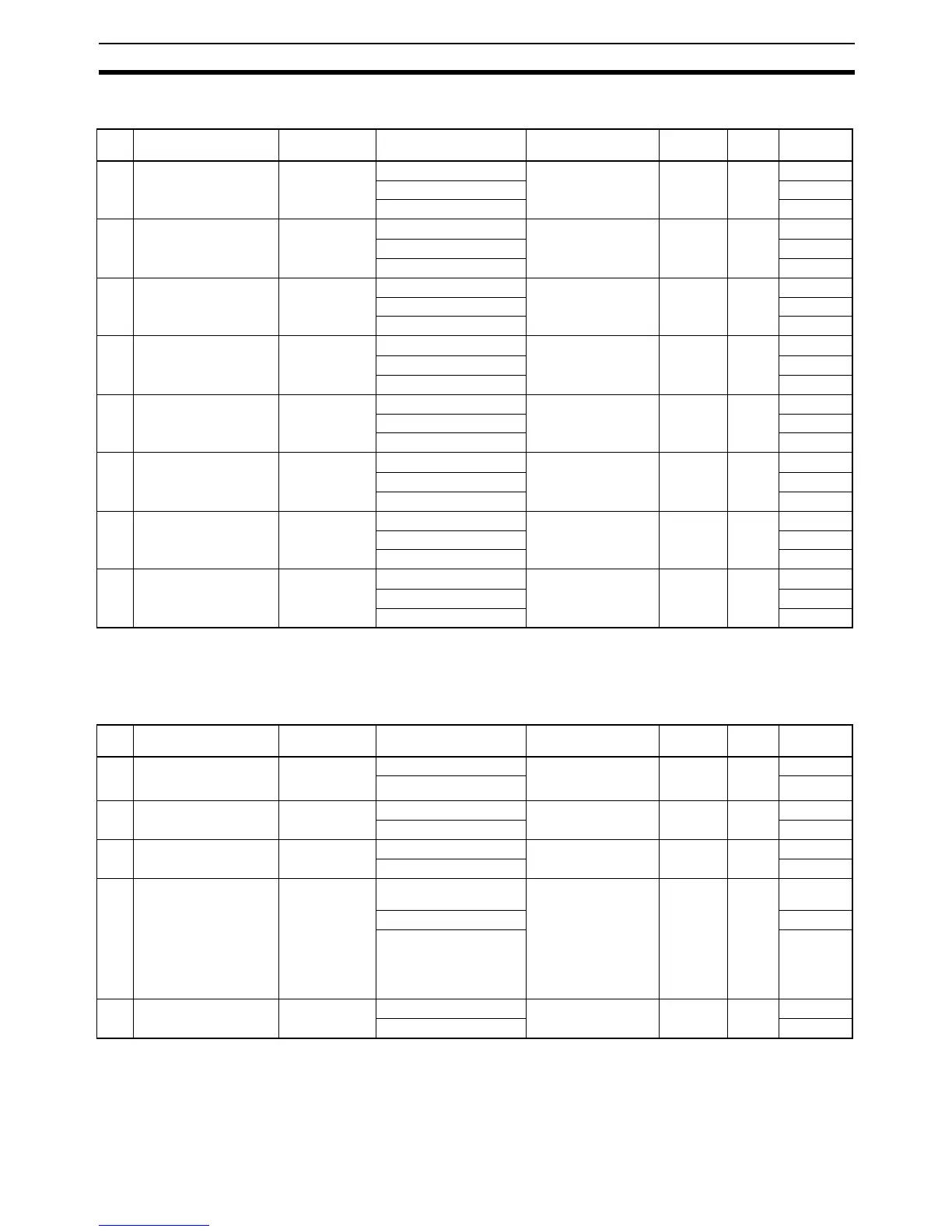
Interrupt Input Settings
Pulse Output 0 Settings
Base Settings
Name Default Settings When setting is read
by CPU Unit
Internal
address
Bits Settings
1IN0
(CIO 0.00)
Normal Normal When power is turned
ON
60 00 to
03
0 hex
Interrupt 1 hex
Quick 2 hex
2IN1
(CIO 0.01)
Normal Normal When power is turned
ON
60 04 to
07
0 hex
Interrupt 1 hex
Quick 2 hex
3IN2
(CIO 0.02)
(Y CPU Units: CIO 1.00)
Normal Normal When power is turned
ON
60 08 to
11
0 hex
Interrupt 1 hex
Quick 2 hex
4IN3
(CIO 0.03)
(Y CPU Units: CIO 1.01)
Normal Normal When power is turned
ON
60 12 to
15
0 hex
Interrupt 1 hex
Quick 2 hex
5IN4
(CIO 1.00)
(Y CPU Units: CIO 1.02)
Normal Normal When power is turned
ON
59 00 to
03
0 hex
Interrupt 1 hex
Quick 2 hex
6IN5
(CIO 1.01)
(Y CPU Units: CIO 1.03)
Normal Normal When power is turned
ON
59 04 to
07
0 hex
Interrupt 1 hex
Quick 2 hex
7IN6
(CIO 1.02)
Normal Normal When power is turned
ON
59 08 to
11
0 hex
Interrupt 1 hex
Quick 2 hex
8IN7
(CIO 1.03)
Normal Normal When power is turned
ON
59 12 to
15
0 hex
Interrupt 1 hex
Quick 2 hex
Name Default Settings When setting is read
by CPU Unit
Internal
address
Bits Settings
1 Undefined Origin (oper-
ation for limit signal turn-
ing ON)
Hold Hold At start of operation 268 12 to
15
0 hex
Undefined 1 hex
2 Limited Input Signal
Operation
Search Only Search Only When power is turned
ON
256 04 to
07
0 hex
Always 1 hex
3 Limit Input Signal NC NC At start of operation 268 00 to
03
0 hex
NO 1 hex
4 Search/Return Initial
Speed
0 pps
(disabled)
0 pps At start of operation 259 and
258
00 to
15
0000 0001
hex
: :
100,000 pps (maximum
for X/XA CPU
Unit)1,000,00 0 pps
(maximum for Y CPU
Unit)
0001 86A0
hex
000F 4240
hex
5 Speed Curve Trapezium Trapezium When power is turned
ON
256 12 to
15
0 hex
S-shaped 1 hex