36
Function Charts Section 1-4
1-4 Function Charts
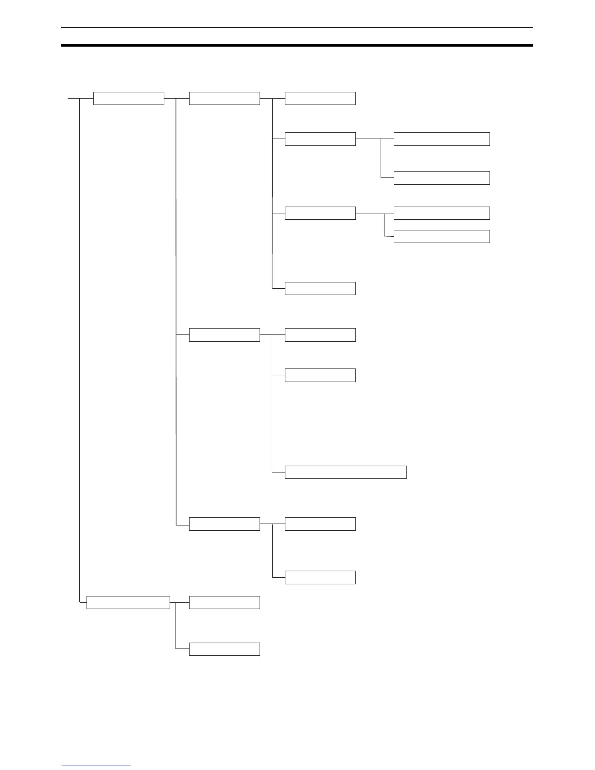
X and XA CPU Units
Built-in I/O functions Built-in input functions
Selected in PLC Setup.
Normal inputs
24 inputs
CIO 0, bits 00 to 11; CIO 1, bits 00 to 11
Immediate refreshing supported.
Interrupt inputs
8 inputs (Interrupt inputs 0 to 7)
CIO 0, bits 00 to 03
CIO 1, bits 00 to 03
Interrupt inputs (Direct mode)
Interrupt task 140 to 147 started
when input turns ON or OFF.
Response time: 0.3 ms
Interrupt inputs (Counter mode)
Interrupt task 140 to 147 started by up or down
counter for input.
Response frequency: 5 kHz total for all interrupts
High-speed counter inputs
4 inputs (High-speed Counter 0 to 3)
CIO 0, bits 08, 09, 03; CIO 0, bits 06, 07, 02
CIO 0, bits 04, 05, 01;
CIO 0, bits 10, 11; CIO 1, bit 00
• Differential phase input: 50 kHz
• Pulse plus direction input: 100 kHz
• Up, down input: 100 kHz
• Increment pulse input: 100 kHz
• Count stopping and starting (Gate function)
• Frequency monitoring (High-speed counter 0 only)
No interrupts
High-speed counter interrupts
• Target value comparison interrupts
• Range comparison interrupts
Quick-response inputs
8 inputs (Quick-response 0 to 7)
CIO 0, bits 00 to 03
CIO 1, bits 00 to 03
Minimum input signal width: 50 µs
Built-in output functions
Selected by instructions.
Normal outputs
16 outputs
CIO 100, bits 00 to 07; CIO 101, bits 00 to 07
Immediate refreshing supported.
Pulse outputs
4 outputs (Pulse outputs 0 to 3)
CIO, 100, bits 00 to 07
Unit version 1.0 and earlier:
1 Hz to 100 kHz: 2 outputs
1 Hz to 30 kHz: 2 outputs
Unit version 1.1 and later:
1 Hz to 100 kHz: 4 outputs
CW/CCW pulse outputs or pulse plus direction outputs
(Pulse outputs 0 and 1 must use the same method.)
• Pulse outputs with no acceleration and deceleration
• Pulse outputs with trapezoidal acceleration and deceleration
Variable duty ratio pulse outputs
(PWM outputs)
2 outputs
CIO 101, bits 00 and 01
Variable duty ratio pulse outputs
Duty ratio: 0.0% to 100.0% (Unit: 0.1%)
Frequency: 0.1 to 6553.5 Hz
Origin functions Origin search
CIO 101, bits 02 to 05: Used as error counter reset output. (Operation
modes 1 and 2 only)
CIO 0 and CIO 1, bits 00 to 03: Used as origin search-related inputs.
• Origin inputs: CIO 0, bits 00, 02; CIO 1, bits 00, 02
• Origin proximity inputs: CIO 0, bits 01, 03; CIO 1, bits 01, 03
Origin return
Execute the ORG instruction to move from any position to the origin.
Built-in analog I/O terminals
(XA models only)
Analog inputs
4 inputs
0 to 5 V, 1 to 5 V, 0 to 10 V, −10 to 10 V, 4 to 20 mA, 0 to 20 mA
Resolution: 1/6,000 or 1/12,000
Conversion time: 1 ms/input
Analog outputs
2 outputs
0 to 5 V, 1 to 5 V, 0 to 10 V, −10 to 10 V, 4 to 20 mA, 0 to 20 mA
Resolution: 1/6,000 or 1/12,000
Conversion time: 1 ms/output