726
PLC Setup Appendix G
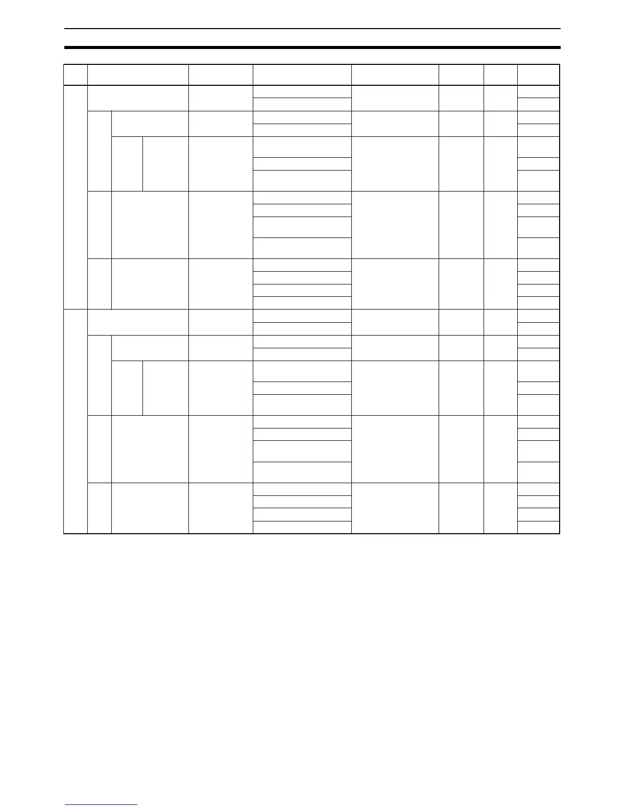
3 Use high speed counter 2 Do not use. Do not use. When power is turned
ON
95 12 to
15
0 hex
Use. 1 hex
3-1 Counting mode Linear mode Linear mode At start of operation 95 08 to
11
0 hex
Circular mode 1 hex
3-1-1 Circular
Max.
Count
0 0 At start of operation 97 and 96 00 to
15
0000
0000 hex
: :
4,294,967,295 FFFF
FFFF hex
3-2 Reset Z phase, soft-
ware reset
Z phase, software reset When power is turned
ON
95 04 to
07
0 hex
Software reset 1 hex
Z phase, software reset
(comparing)
2 hex
Software reset
(comparing)
3 hex
3-3 Input Setting Differential
phase input
Differential phase input When power is turned
ON
95 00 to
03
0 hex
Pulse + direction input 1 hex
Up/Down input 2 hex
Increment pulse input 3 hex
4 Use high speed counter 3 Do not use. Do not use. When power is turned
ON
98 12 to
15
0 hex
Use. 1 hex
4-1 Counting mode Linear mode Linear mode At start of operation 98 08 to
11
0 hex
Circular mode 1 hex
4-1-1 Circular
Max.
Count
0 0 At start of operation 100 and
99
00 to
15
0000
0000 hex
: :
4,294,967,295 FFFF
FFFF hex
4-2 Reset Z phase, soft-
ware reset
Z phase, software reset When power is turned
ON
98 04 to
07
0 hex
Software reset 1 hex
Z phase, software reset
(comparing)
2 hex
Software reset
(comparing)
3 hex
4-3 Input Setting Differential
phase input
Differential phase input When power is turned
ON
98 00 to
03
0 hex
Pulse + direction input 1 hex
Up/Down input 2 hex
Increment pulse input 3 hex
Name Default Settings When setting is read
by CPU Unit
Internal
address
Bits Settings