725
PLC Setup Appendix G
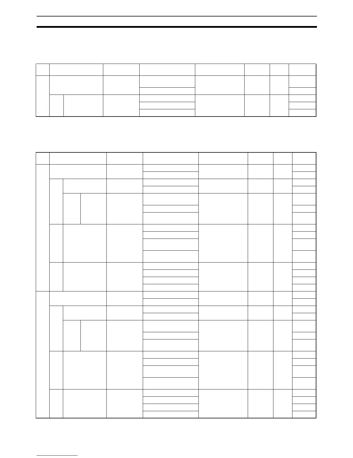
Peripheral Service Settings
Set Time to All Events: Time Setting for Services
Built-in Input Settings
High Speed Counter Settings
Name Default Settings When setting is read
by CPU Unit
Internal
address
Bits Settings
1 Set time to all events Default Default
(4% of cycle time)
At start of operation 218 15 0
Use user setting. 1
1-1 Time allocated to
services
0: 0 × 0.1 ms =
0 ms
0: 0 × 0.1 ms = 0 ms At start of operation 218 00 to
07
00 hex
: :
255: 255 × 0.1 ms FF hex
Name Default Settings When setting is read
by CPU Unit
Internal
address
Bits Settings
1 Use high speed counter 0 Do not use. Do not use. When power is turned
ON
50 12 to
15
0 hex
Use. 1 hex
1-1 Counting mode Linear mode Linear mode At start of operation 50 08 to
11
0 hex
Circular mode 1 hex
1-1-1 Circular
Max.
Count
0 0 At start of operation 52 and 51 00 to
15
0000
0000 hex
: :
4,294,967,295 FFFF
FFFF hex
1-2 Reset Z phase, soft-
ware reset
Z phase, software reset When power is turned
ON
50 04 to
07
0 hex
Software reset 1 hex
Z phase, software reset
(comparing)
2 hex
Software reset (compar-
ing)
3 hex
1-3 Input Setting Differential
phase input
Differential phase input When power is turned
ON
50 00 to
03
0 hex
Pulse + direction input 1 hex
Up/Down input 2 hex
Increment pulse input 3 hex
2 Use high speed counter 1 Do not use. Do not use. When power is turned
ON
53 12 to
15
0 hex
Use. 1 hex
2-1 Counting mode Linear mode Linear mode At start of operation 53 08 to
11
0 hex
Circular mode 1 hex
2-1-1 Circular
Max.
Count
0 0 At start of operation 55 and 54 00 to
15
0000
0000 hex
: :
4,294,967,295 FFFF
FFFF hex
2-2 Reset Z phase, soft-
ware reset
Z phase, software reset When power is turned
ON
53 04 to
07
0 hex
Software reset 1 hex
Z phase, software reset
(comparing)
2 hex
Software reset (compar-
ing)
3 hex
2-3 Input Setting Differential
phase input
Differential phase input When power is turned
ON
53 00 to
03
0 hex
Pulse + direction input 1 hex
Up/Down input 2 hex
Increment pulse input 3 hex