445
CompoBus/S I/O Link Units Section 7-6
Specifications
LED Indicators
CP1W-SRT21/CPM1A-SRT21 CompoBus/S I/O Link Unit
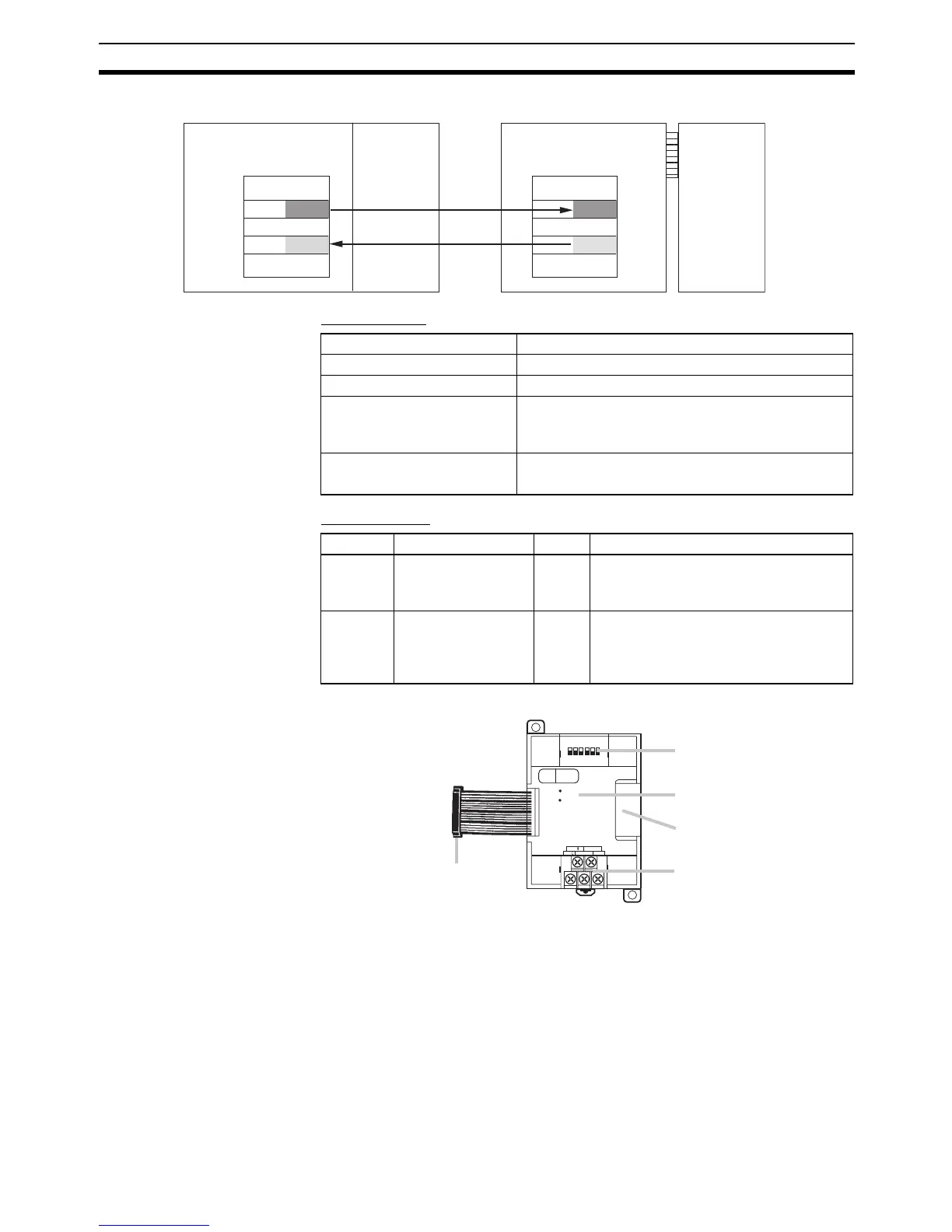
(1) CompoBus/S Terminals
The following CompoBus/S terminals are provided: CompoBus/S com-
munications data high/low terminals, NC terminals for communications
power supply plus (+) and minus (-), and an NC terminal. (Power is sup-
plied internally for this Unit, so the NC terminals for communications
power supply can be used as relay terminals.)
Master PC (CS Series)
CPU Unit
CP1H
I/O memory
Input
CIO 2
Output
CIO 12
8 bits
8 bits
I/O memory
Input
CIO 2004
Output
CIO 2000
8 bits
8 bits
CompoBus/S
Master Unit
Unit No. 0
CompoBus/S
I/O Link Unit
Node
number: 0
Model number CP1W-SRT21/CPM1A-SRT21
Master/slave CompoBus/S Slave
Number of I/O points 8 input points, 8 output points
Number of words allocated in
CPU Unit I/O memory
1 input word, 1 output word
(Allocated in the same way as Expansion Units and
Expansion I/O Units.)
Node number setting Set using the DIP switch
(Set before turning on the CPU Unit’s power supply.)
Indicator Name Color Meaning
COMM Communications
Indicator
Yellow ON: Communications in progress.
OFF: Communications stopped or error
has occurred.
ERR Error indicator Red ON: A communications error has
occurred.
OFF: Indicates normal communications
or stand-by.
BD NC( BS-) NC
BD NC( BS+)
S
COMM
ERR
ON
132
4
5
6
No.
SRT21
EXP
(1) CompoBus/S Terminals
(3) LED Indicators
(4) Expansion I/O Connecting Cable
(5) Expansion Connector
(2) DIP Switch