4-3 Manually Setting Data Links
4-3-2 Creating Data Link Tables
4-3-2 Creating Data Link Tables
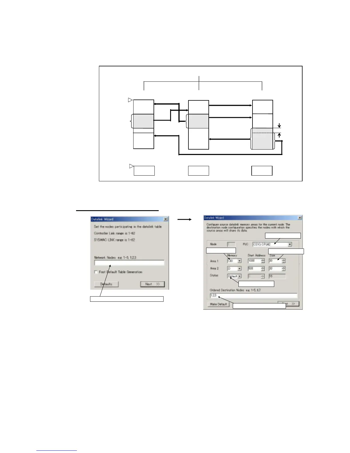
Create a data link table for each node registered in the CX-Server file that is read.
Make the settings for (1) to (8) below.
Node 2
(receive)
(3)
Area setting
(area/start
address)
(4) Send size
(2) Node 1
PLC type
Node 1
(send)
Node 3
(receive)
(7) Receive
sizes from
remote nodes
(5) Node refresh sequence:
2, 1, 3 1, 2, 3 2, 1, 3
(6)
Status area
Node 3
(receive)
Node 3
(send)
Node 2
(send)
Node 1
(receive)
Node 1
(receive)
Node 2
(receive)
Data link
status
Data link
status
Data link
status
Node 2
PLC
Node 3
PLC
(8) Offsets
(1) Participating data link nodes
To create a data link table, make the following settings in order.
1. Datalink Wizard Settings
(1) Set participating data link nodes.
(2) Set the PLC type.
(3) Set the areas.
(6) Set the status area.
(5) Set the refresh node sequence.
(4) Set the send size.
4-9
 Loading...


