4-4 Automatically Set Data Links
4-4-2 Controller Link Automatic Setup
Common Type
(2)
(3)
(5)
(6)
(8)
(7)
(1)
(4)
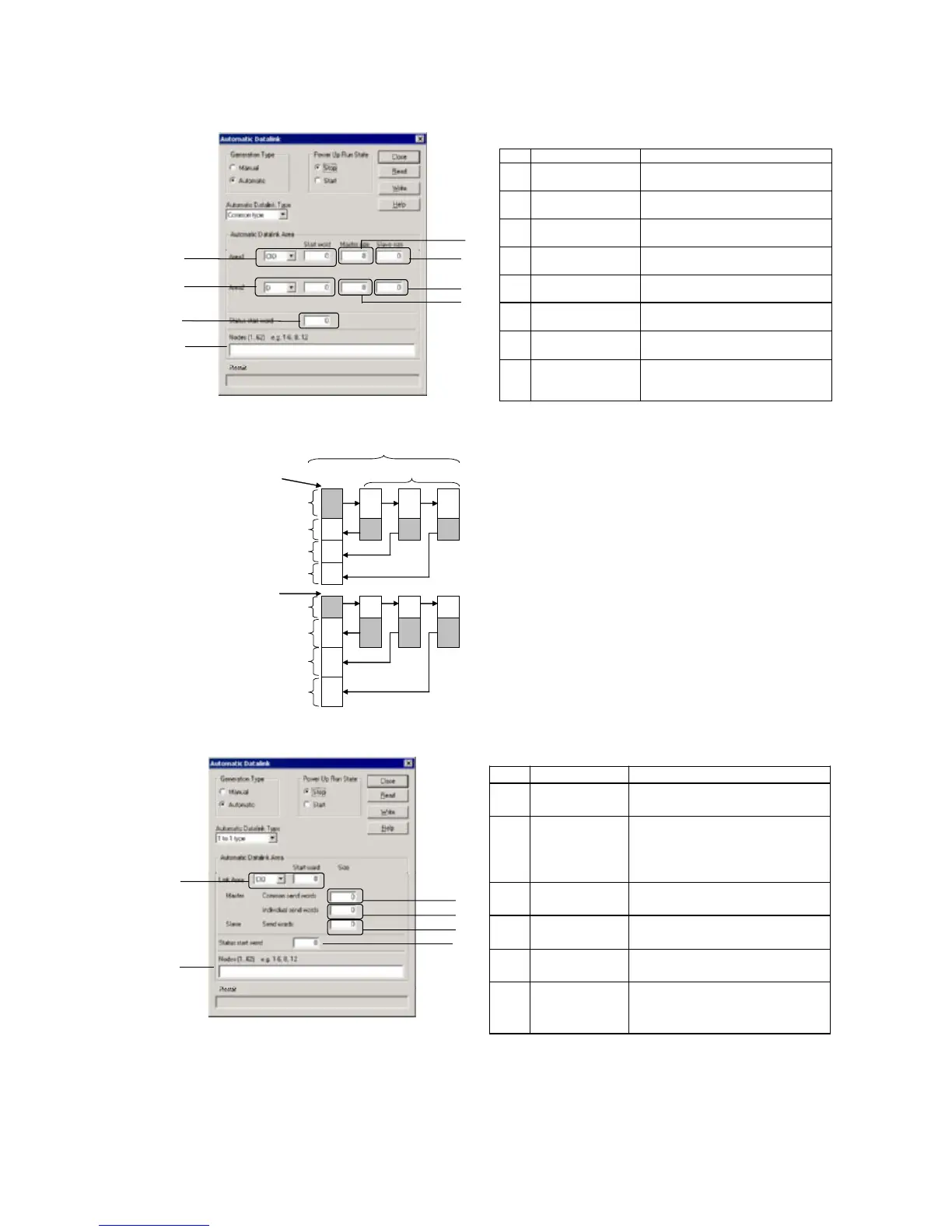
Common Type Settings
No. Item Description of function
(1) Area and Start Word
for Area 1
Set the area and the start data link word
to use for area 1.
(2) Master size Set the area 1 send size for the master
node.
(3) Slave size Set the area 1 send size for the slave
node.
(4) Area and Start Word
for Area 2
Set the area and the start data link word
to use for area 2.
(5) Master size Set the area 2 send size for the master
node.
(6) Slave size Set the area 2 send size for the slave
node.
(7) Nodes Set the nodes to participate in the data
links.
(8) Status start word Set the first word to store data link status.
(If 0 words is set, the default area will be
used.)
Area 1
1
4
1
2 2
3
1 1
3 4
Area 2
1
4
1
2 2
3
1 1
3 4
Master node Slave node
(7) Participating nodes
Area 1
(1) Area and Start Word
Area 2
(4) Area and Start Word
(2) Master size
(3) Slave size
(Same as (3).)
(Same as (3).)
(5) Master size
(6) Slave size
(Same as (6).)
(Same as (6).)
Features of Common Type 1:N Allocation
•
Data communications are 1:1 between the master node and slave nodes.
•
All slave nodes receive the data sent by the master node.
•
The master node receives all data sent by the slaves. The reception siz
for the master node is thus the node send data size times the number o
slave nodes.
•
Slaves do not send or receive data with other slaves.
•
Area 1 is selected from the bit-access areas (e.g., CIO Area) and area 2 is
selected from word-access areas (e.g., DM Area).
•
Data link areas are allocated in ascending order of node addresses.
•
Data link participation can be specified for each node.
•
The same area classification can be used for both Area 1 and Area 2,
provided that the same addresses are not used (CS/CJ-series Controlle
Link Units with unit Ver. 1.2 or later).
1 to 1 Type
(2)
(3)
(4)
(1)
(6)
(5)
1 to 1 Type Settings
No. Item Description of function
(1) Link Area and
Start Word
Set the area and start data link word.
(2) Master, Common
Send Words
Set the send size of the data to send
from the master node to all slave
nodes. The same size of data is sent to
all nodes.
(3) Master, Individual
Send Words
Set the send size for the master node
to sent individually to each slave node.
(4) Slave, Send
Words
Set the send size of the data sent from
each slave node to the master node.
(5) Nodes Set the nodes participating in the data
links.
(6)
Status start
word
Set the start word to store data link
status. (If 0 words is set, the default
area will be used.)
4-45
 Loading...


