9-1 Controller Link Network Diagnostic Tool
9-1-1 Diagnostic Functions and Flowcharts
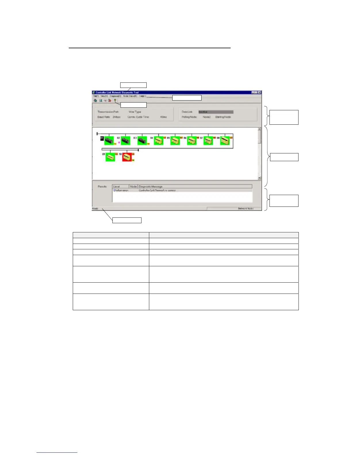
Components of the Network Diagnosis Tool Window
This section describes the various components of the Controller Link Network
Diagnostic Tool Window.
Main Window
Component Names and Functions
(6) Diagnostic
results area
(5) Node list area
(7) Status bar
(2) Menu bar
(3) Tool bar
(1) Title bar
(4) Shared
network
information
area
Name Function
(1) Title bar Displays the file name when a node file is selected.
(2) Menu bar Use to select a menu.
(3) Tool bar Select a function by clicking an icon.
(4) Shared network information
area
Displays shared Controller Link network information, such as the
transmission path and communications cycle time.
(5) Node list area Displays the node configuration of the Controller Link network, which
was read by executing the network status diagnosis operation.
The node status is indicated by the color of its bitmap icon.
(6) Diagnostic results area Displays the results of the network status diagnosis.
Double-click an item to view detailed results.
(7) Status bar Displays information such as the network address and node address
of the node to which the Controller Link Network Diagnostic Tool is
connected.
9-4
 Loading...


