1-5 Window Descriptions
1-5-2 Main Window
Relay PLC Communications Settings
Display format: Offline, Network Type, COM Port No., Baud Rate, Parity, Data Bits, Stop Bits
[relay PLC’s CPU Unit model] Net (Network Address) Node (Node Address)
Description:
Display item Network Type
COM Port
No.
Baud Rate Parity Data Bits Stop Bits
Contents The following network
types will be displayed for
the connection to the
relay PLC.
Toolbus (peripheral)
SYSMAC WAY (Host
Link)
SYSMAC LINK
Ethernet
Ethernet (FINS/TCP)
FinsGateway
Controller Link
COM port on
computer
(Displayed
only for
Toolbus or
SYSMAC
WAY)
Baud rate is
displayed in
bits/s.
(Displayed
only for
SYSMAC
WAY)
The
communicatio
ns data
format parity
is displayed.
Even, Odd, or
None
(Displayed
only for
SYSMAC
WAY)
7 or 8
(Displayed
only for
SYSMAC
WAY)
1 or 2
Example Toolbus COM1, 19200, None, 8, 1
Display item
Relay PLC’s CPU Unit
model
Relay PLC’s FINS destination
network address (decimal)
Relay PLC’s FINS destination node
address (decimal)
Example [CS1H-CPU67H] Net (0) Node (0)
Contents Relay PLC’s CPU Unit
model
For a direct serial connection, the FINS destination network and node addresses
are normally displayed as 0.
For direct network connections, any FINS destination network (1 to 127) and
node addresses can be set. (If routing tables are registered in the PLCs on the
networks, specifying a PLC on any network other than the network that is
directly connected to is also possible.
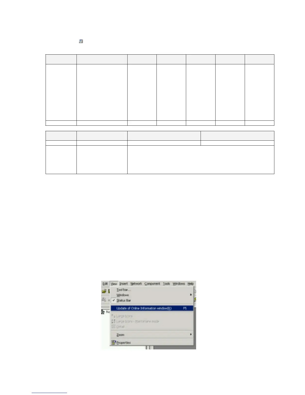
Updating the Online Connection Information Window Display
This section describes how to update the target PLC display in the Online Connection
Information Window display, and how to display the updated information.
!Caution When changing or removing a routing table (see note), be sure to update the
display for the Online Connection Information Window. The display for the
Online Connection Information Window could possibly be different from the ac-
tual network status. If operations are executed without first updating the display,
particularly online operations in the Network Configuration Window, it could
cause data to be mistakenly read or written for the wrong network or node ad-
dress or unit number.
Note: Changing or removing a routing table refers to using the CX-Integrator (or a
CX-Integrator for another personal computer) to start the Routing Table
Component and then changing or removing a routing table for the target PLC
(either a local network table or a relay network table).
Use the following procedure.
1. In the Online Connection Information Window, either select Update of Online
Information Window from the View Menu or press the F5 Key.
1-27
 Loading...


