used to calculate the measurement interval that allows logging without affecting the processing time is
described below.
l
Measurement Interval Conditions
The measurement interval must satisfy the following condition.
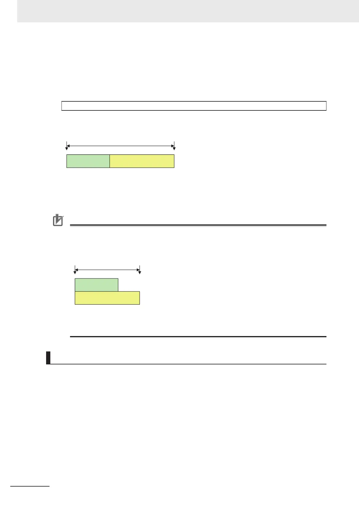
Processing time + Image logging time < Measurement interval
• Processing time: The time that is displayed in the upper left corner.
• Image logging time: The time that is required to generate and save a single image file.
Measurement interval
Processing time Image logging time
Example:
If the processing time is 100 ms and the image logging time is 150 ms, set the measurement inter-
val to at least 250 ms.
Precautions for Correct Use
Standard is selected for Operation Mode.
In Standard (Operation) mode, images can be logged while measurement is in progress.
The measurement interval must satisfy the following condition.
Processing time + Image logging time < Measurement interval
Processing time
Image Logging
Measurement interval
• Example:
If the processing time is 100ms and the image logging time is 150ms, set the measurement
interval to at least 150ms.
Specifying Logging Conditions for Images
If you need to specify conditions for logging images, you should use the processing item logging func-
tion.
For example, the system logging function logs all images if the overall judgement is NG or OK.
Processing item logging (image logging), logs images only when a condition is met.
The following examples illustrate how processing item logging can be used.
l
Possible Saving Conditions
Images can be logged when measurement data or result data of a calculation falls within a speci-
fied range.
Example 1: Image logging is performed if the individual judgements of three measurement units
U1, U3, and U5 are NG.
6 Performing Measurement and Adjustment
6 - 18
FH/FHV Series Vision System User’s Manual (Z365-E1)
 Loading...


