8-3
Arranging Windows [Layout Func-
tions]
8-3-1
Arranging Window Elements [Layout Modification]
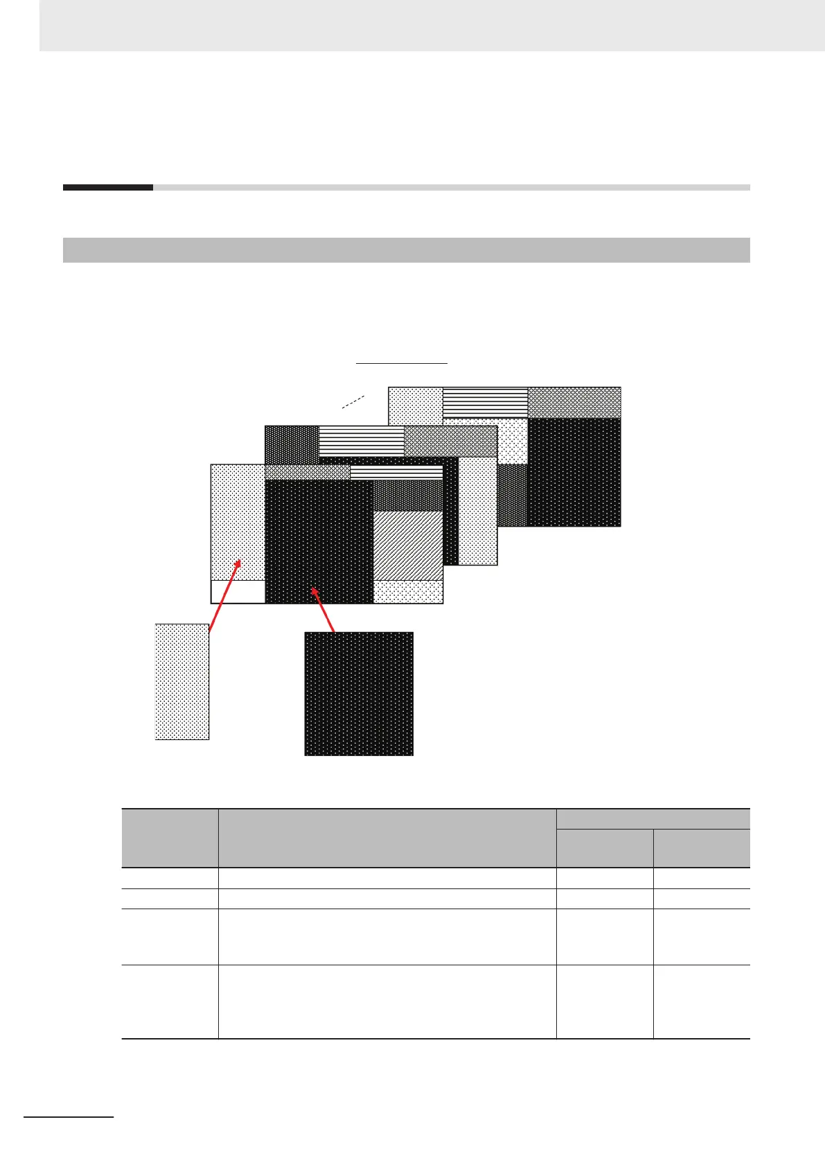
Configuration elements for the Main Windows (called window parts) can be laid out and displayed any-
where.
You can create a maximum of 9 Main Windows from layout 0 to layout 8.
Flow Display Pane
Image Pane or other pane
ows
Window parts can be placed anywhere.
Layout 0
Layout 1
Layout 8
Each Layout Window is set as follows by default:
Layout Default setting
Behavior of output signals
RUN signal
output
Signal output
of results
Layout 0 Layout 0 is set as an adjustment window. OFF OFF
Layout 1 Layout 1 is set as a run window. ON ON
Layout 2 to
Layout 7
Layouts 2 to 7 are for user-defined purposes and are creat-
ed as they are needed. By default, these layouts have the
same settings as layout 0.
OFF OFF
Layout 8
Layout 8 is set as a remote operation window.
When an error occurs in Layout 8, error dialog appears as
a text string in the Error Pane instead of in an error dialog
box.
OFF OFF
8 Setting Windows
8 - 12
FH/FHV Series Vision System User’s Manual (Z365-E1)
 Loading...


