Main
menu
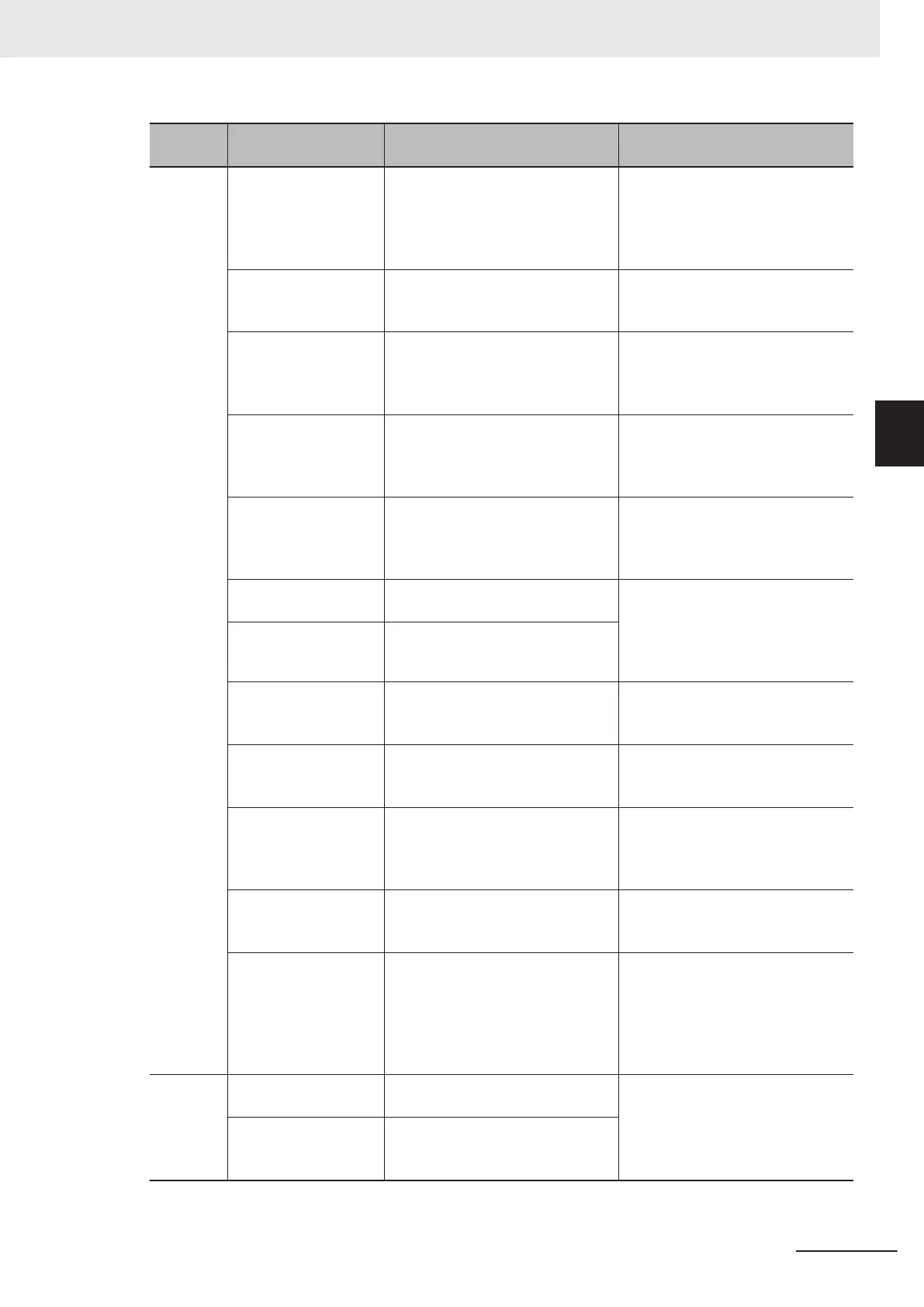
Command Description Reference
Communication com-
mand macro
Creates a communication unit
(Communication custom command)
customized by user for FH/FHV
series from external devices such
as PLC.
10-7 Customizing Communication
Commands [Communication Com-
mand Macro] on page 10 - 50
Flow viewer Shows the flow of processing for
the measurement flow that is cur-
rently being edited.
5-4 Displaying and Checking Proc-
essing Branches in a Scene on
page 5 - 10
Calibration support
tool
Graphically displays the relation-
ship of the positions of the Camera
coordinates and the actual coordi-
nates.
6-7 Verifying Calibration Results
[Calibration Support Tool] on page
6 - 43
Update standard posi-
tion tool
Sets or changes the reference posi-
tion for more than one processing
unit specified in the measurement
flow.
6-5 Updating the Reference Posi-
tion Data for a Unit in the Measure-
ment Flow [Update Standard Posi-
tion Tool] on page 6 - 34
Conversion scene
group data tool
Creates a scene group that has
more than 129 scenes.
7-6 Increasing the Number of
Scenes in a Group to more than
128 Scenes [Conversion scene
group data tool] on page 7 - 14
Custom dialog tool Used to create customized dialog
boxes for setting processing items.
8-4 Editing contents are not reflect-
ed when you confirm the Sensor
Controller after edit a layout by re-
mote control [Custom Dialog Tool]
on page 8 - 64
Custom dialog Displays a dialog box that is creat-
ed with the custom dialog tool.
Scene control macro
tool
Complements or extends the oper-
ation of the measurement flow or
scene.
10-9 Positioning workpieces for
stage and robot applications [Align-
ment Function] on page 10 - 52
Configuration copy Saves and loads all the various set-
tings data files saved in the Sensor
Controller.
9-7 Backing up Sensor Controller
Setting Data [Configuration Copy]
on page 9 - 15
Line maintenance This tool can be used when using
Multi-line random-trigger mode to
copy settings data from one line to
another line.
9-8 Copying Settings for Each Line
in Multi-line Random-trigger Mode
[Line Maintenance] on page 9 - 32
Keyboard layout selec-
tion tool
Sets the keyboard arrangement for
the controller software keyboard or
for a USB connected keyboard.
10-5 Setting the Keyboard Layout
for the Controller [Keyboard Layout
Selection Tool] on page 10 - 46
Device information
storage tool
This tool will prevent issues hap-
pening at start-up of the Sensor
Controller due to recognition delay
for external devices. Be sure to ex-
ecute this tool when connecting ex-
ternal devices.
3-6 Saving Settings before Turning
OFF the Power and Restarting on
page 3 - 31
Window Layout modification Used to change any layout from
layout 0 to layout 8.
8-3 Arranging Windows [Layout
Functions] on page 8 - 12
Layout setup Sets whether to use the RUN signal
output and external outputs for lay-
outs 0 to 8.
Appendices
A - 5
FH/FHV Series Vision System User’s Manual (Z365-E1)
A-1 Menu List
A
 Loading...


