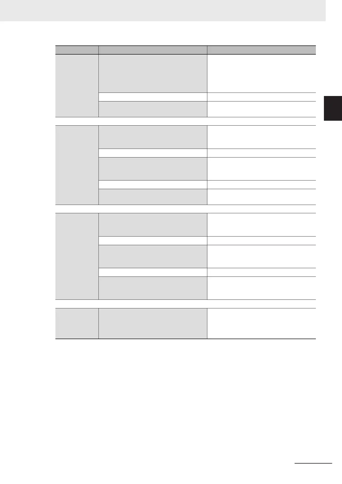
Procedure Description Reference
Scene Editing In the Main Window (layout 0), edit the
measurement flow.
• Register processing items.
• Set the properties for each processing
item.
Refer to Section 5 Creating Measurement
Scenes on page 5 - 1.
↓
Click the Data save button. Refer to 9-2 Saving Settings Data to the
Flash Memory on page 9 - 7.
↓↑
Testing Execute test measurements.
(In the Main Window (layout 0), click the
Measure button.)
Refer to 6-1 Executing Test Measurements
on page 6 - 2.
↓
Adjust the parameters for each processing
item.
Refer to Vision System FH/FHV Series
Processing Item Function Reference Manual
(Cat. No. Z341).
↓
Click the Data save button. Refer to 9-2 Saving Settings Data to the
Flash Memory on page 9 - 7.
↓
Measuring (Op-
eration)
In the Main Window (layout 0), click the
Switch layout button, and then select Main
Window (Layout 1).
Refer to Section 6 Performing Measurement
and Adjustment on page 6 - 1.
↓
In the Main Window (layout 1), check the
communications with the PLC.
Refer to Vision System FH/FHV Series
User's Manual for Communications Settings
(Cat. No. Z342).
↓
In the Main Window (layout 1), execute com-
mands from the PLC, such as measurement
trigger commands.
Refer to Vision System FH/FHV Series
User's Manual for Communications Settings
(Cat. No. Z342).
↓
Management
and Analysis
Save and analyze measurement data and
images.
Refer to 6-4 Analyzing Inspection and Meas-
urement Results [NG Analyzer] on page
6 - 26, Section 9 Saving/Loading Data on
page 9 - 1.
1 Overview
1 - 7
FH/FHV Series Vision System User’s Manual (Z365-E1)
1-2 Flow of Application
1
 Loading...


