Sensor Controller cam-
era connector number
Camera number in application software
Example when all cam-
eras use one-cable
connection
Example when all cam-
eras use two-cable
connection
Example when combin-
ing one- and two-cable
connection
0 0 0 0
1 1 1
2 2 2 2
3 3
4 4 4 Not connected
5 5 5
6 6 6 6
7 7
l
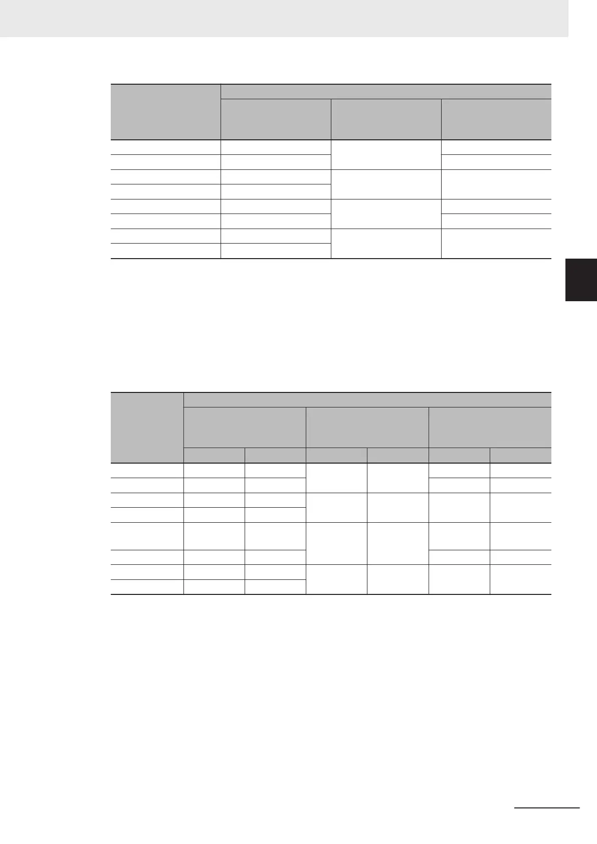
Camera numbers for multi-line random trigger mode
The table below shows the camera connector and camera number assignments when the opera-
tion mode is the multi-line random trigger mode. This table is an example showing the camera
number assignments when the number of lines is two.
Camera numbers are assigned for each line in ascending order starting from 0. For two-cable con-
nection, camera numbers are assigned in ascending order regardless of camera connector number
pairs.
Sensor Con-
troller camera
connector
number
Camera number in application software
Example when all cam-
eras use one-cable con-
nection
Example when all cam-
eras use two-cable con-
nection
Example when combining
one- and two-cable con-
nection
Line 0 Line 1 Line 0 Line 1 Line 0 Line 1
0 0 - 0 - 0 -
1 1 - 1 -
2 2 - 2 - 2 -
3 3 -
4 - 0 - 0 - Not connect-
ed
5 - 1 - 0
6 - 2 - 2 0 1
7 - 3
3 Basic Operations
3 - 3
FH/FHV Series Vision System User’s Manual (Z365-E1)
3-1 Preparing the Controller and Cameras
3
3-1-1 Camera Setup
 Loading...


