Controlling Operation and Outputting Data with a Parallel Interface Sensor Data Unit
264
FQ2 User’s Manual
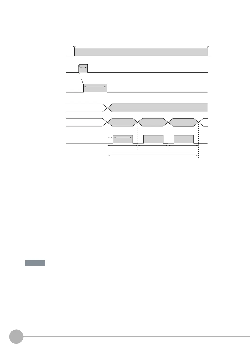
● Single Measurement
Example: Three Data Items Set for Parallel Data Output
Timing Chart
1 The RUN signal turns ON when measurements are enabled and the Sensor is in Run Mode.
2 Turn ON the TRIG signal while the BUSY signal is OFF.
3 Measurement begins and the BUSY signal is turned ON during the measurement process.
4 When the measurement has been finished, the measurement results are output using an OR sig-
nal and the D0 to D15 signals, and the BUSY signal is turned OFF.
*1
*1 You can also set the [BUSY output] parameter so that the BUSY signal is turned OFF after the completion of data logging, image logging,
or displaying results.
5 After the BUSY signal turns OFF, the GATE signal is turned ON when the time that is set in the
[GATE ON delay] parameter in the communications settings has elapsed.
*2
6 The GATE signal is turned ON, and then the GATE signal is turned OFF when the time that is set
in the [Output time] parameter in the communications settings has elapsed.
*2
*2 Set the GATE ON delay and output time for the GATE signal so that the total time does not exceed the output period.
Data Output Time and TRIG Signal Input Interval
Set the input interval for the TRIG signal so that it is equal to or greater than the total output time. If the input
interval for the TRIG signal is shorter than the total output time, the output data buffer will eventually overflow
and output data will be discarded.
Turned ON when overall judgement is NG.
(Polarity of all output signals: Positive)
Data 0
Data 1
Data 2
Output time
Output period
The total output time is as follows: Output period × Number of output data items.
GATE ON delay
TRIG signal
OFF
ON
OFF
ON
ON for 1 ms min.
BUSY signal
OFF
ON
OFF
ON
OR signal
D0 to D31
signals
GATE signal
ON while measurements are being processed
(depends on BUSY output conditions)
Run Mode entered.
RUN signal
Setup Mode entered.
Important