Controlling Operation and Outputting Data with a Parallel Interface Sensor Data Unit
FQ2 User’s Manual
269
8
Controlling Operation and Outputting Data
with a Parallel Connection
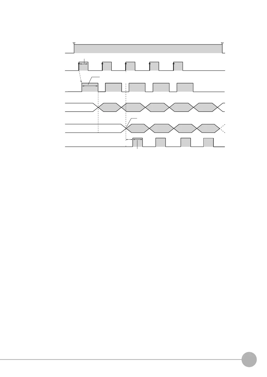
● Timing Chart
Operation When [Number of Delay] Is Set to 2
1 Repeatedly turn ON the TRIG signal while the BUSY signal is OFF.
2 The OR signal is output when the TRIG signal is turned ON.
3 When the TRIG signal turns ON for the third time, the measurement result (D0) for the first time
that the TRIG signal turned ON is output and the GATE signal is also output at this time.
4 When the TRIG signal turns ON for the fourth time, the measurement result (D0) for the second
time that the TRIG signal turned ON is output and the GATE signal is also output at this time.
5 Each time the TRIG signal turns ON after that, the measurement result (D0) from when the TRIG
signal turned ON two times previously is output.
(Result not
output.)
The results for (1) is output when the TRIG signal
turns ON the third time.
Result for (1) Result for (2) Result for (3) Result for (4)
(1) (2) (3) (4) (5)
TRIG signal
OFF
ON
OFF
ON
OFF
ON
OFF
ON
ON for 1 ms min.
BUSY signal
OR signal
D0 signal
GATE signal
Run Mode entered.
RUN signal
Setup Mode entered.
GATE ON delay
Output time
ON while measurements are being processed
(depends on BUSY output conditions)
Overall judgement
result for (1)
Overall judgement
result for (2)
Overall judgement
result for (3)
Overall judgement
result for (4)
Overall judgement
result for (5)