PLC Link Connections
328
FQ2 User’s Manual
Item
Description Setting range
Command (com-
mand area)
Area type Select the area for the
Command Area in the
PLC.
If PLC Link (SYSMAC) is selected:
CIO Area (CIO)
Work Area (WR)
Holding Bit Area (HR)
Auxiliary Bit Area (AR)
DM Area (DM)
EM Area (EM0 to EMC)
Default: CIO Area (CIO)
If PLC Link (MELSEC) is selected:
Data Register (Data registers)
File Register (File registers)
Link Register (Link registers)
Default: Data Register
Address
Set the first address of the
command area in the PLC.
0 to 99,999
Default: 0
Response
(response area)
Area type
Set the PLC memory area
for the response area.
Same as for the Command Area.
Address
Set the first address of the
response area in the PLC.
0 to 99,999
Default: 100
Output (output
area)
Area type
Set the PLC memory area
for the output area.
Same as for the Command Area.
Address
Set the first address of the
output area in the PLC.
0 to 99,999
Default: 200
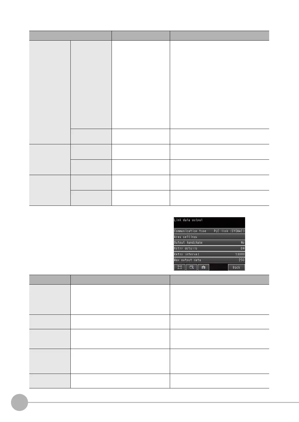
4 Set the communications protocol ([Communication
type]) to PLC Link communications.
Item
Description Setting range
Output handshake Enables or disables handshaking.
• Yes: Data is output when the DSA signal
from the PLC turns ON.
• No: Data is output regardless of the signal
state from the PLC.
No or Yes
Default: No
Retry details Enables or disables retrying communications. ON or OFF
Default: OFF
Retry interval Sets the interval for retrying communications.
This setting is enabled only when [Retry details]
is set to [ON].
0 to 2,147,483,647 ms
Default:10,000 ms
Max output data Sets the maximum data size that can be output
at one time through PLC Link communications.
Set the number of bytes. Any output data that is
beyond this value is discarded.
32 to 1,024 bytes
Default: 256 bytes
Connection mode Sets the TPC connection mode. TCP server or TCP client
Default: TCP server