3 - 29
3 Part Names and Functions
NX-series Safety Control Unit User’s Manual (Z930)
3-3 Safety I/O Functions
3
3-3-1 Safety Input Functions
• Relationship between Input Signals to Safety Input Terminals and Safety Input Data for
Dual-channel Inputs
• Relationship between Safety Mat Status and Safety Input Data for Safety Mat/Safety Edge Inputs
• Operation for Single Channel: Normal Operation
Single/Dual
Input signal on the
safety input terminals
Safety input data
Meaning of status
Si (x) Si (x)
Single Channel 0 0 Inactive (OFF)
1 1 Active (ON)
Single/Dual
Input signals on the
safety input terminals
Safety input data
Meaning of status
Si (n) Si (n+1) Si (n) Si (n+1)
Dual Channel Equiv-
alent
000
0
*1
*1. If the terminals are set to Dual Channel Mode, the safety program in the Safety CPU Unit must access the
safety input data for the even-numbered terminal.
Inactive (OFF)
010
0
*1
Discrepant status
100
0
*1
Discrepant status
111
0
*1
Active (ON)
Dual Channel Com-
plementary
000
0
*1
Discrepant status
010
0
*1
Inactive (OFF)
101
0
*1
Active (ON)
110
0
*1
Discrepant status
n = Even number
Single/Dual
Safety mat/safety edge
status
Safety input data
Meaning of status
Si (n) Si (n+1)
Safety Mat/Safety Edge Without load 1
0
*1
*1. If the terminals are set to Dual Channel Mode, the safety program in the Safety CPU Unit must access the
safety input data for the even-numbered terminal.
Active (ON)
With load 0
0
*1
Inactive (OFF)
n = Even number
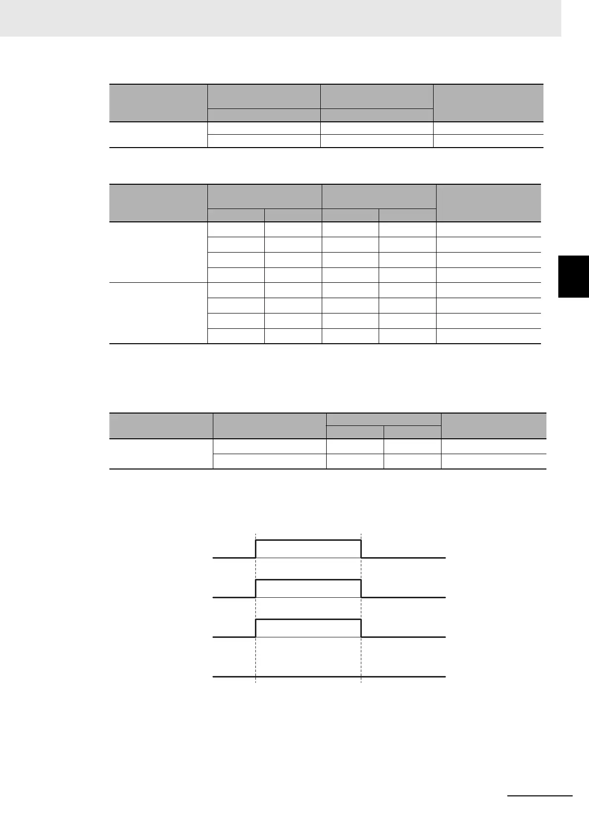
Safety input terminal
Safety input data
I/O indicator (yellow)
I/O indicator (red)
OFF ON OFF