2 - 3
2 Specifications
NX-series Safety Control Unit User’s Manual (Z930)
2-2 Specifications of Individual Units
2
2-2-1 Models
2-2 Specifications of Individual Units
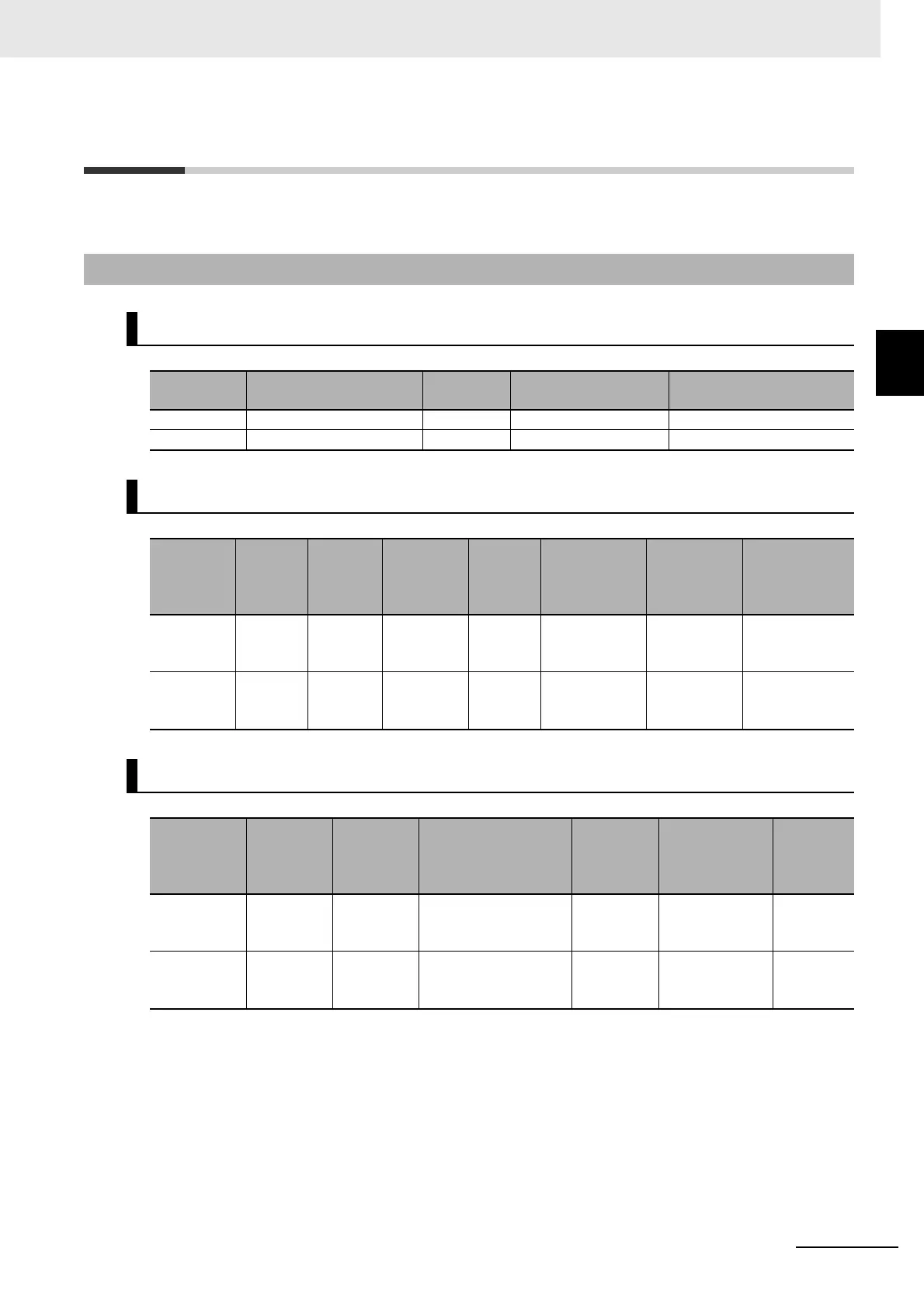
This section gives the specifications of the NX-series Safety CPU Unit and the Safety I/O Units.
2-2-1 Models
Safety CPU Unit
Model
Maximum number of
safety I/O points
Program
capacity
Number of safety
master connections
I/O refreshing method
NX-SL3300 256 points 512 KB 32 Free-Run refreshing only
NX-SL3500 1,024 points 2,048 KB 128 Free-Run refreshing only
Safety Input Units
Model
Number
of safety
input
points
Number
of test
output
points
Internal I/O
common
Rated
input
voltage
OMRON
Special
Safety Input
Devices
Number of
safety slave
connections
I/O refreshing
method
NX-SIH400 4 points 2 points Sinking
inputs
(PNP)
24 VDC Can be con-
nected.
1 Free-Run
refreshing only
NX-SID800 8 points 2 points Sinking
inputs
(PNP)
24 VDC Cannot be
connected.
1 Free-Run
refreshing only
Safety Output Units
Model
Number of
safety out-
put points
Internal I/O
common
Maximum load
current
Rated
voltage
Number of
safety slave
connections
I/O
refresh-
ing
method
NX-SOH200 2 points Sourcing
outputs
(PNP)
2.0 A/point, 4.0 A/Unit
at 40°C, and 2.5
A/Unit at 55°C
24 VDC 1 Free-Run
refreshing
only
NX-SOD400 4 points Sourcing
outputs
(PNP)
0.5 A/point and 2.0
A/Unit
24 VDC 1 Free-Run
refreshing
only