3 Part Names and Functions
3 - 6
NX-series Safety Control Unit User’s Manual (Z930)
3-2 Safety I/O Units
This section gives the names of the parts of the Safety I/O Units and describes the operation indicators,
terminal block layouts, and safety I/O functions.
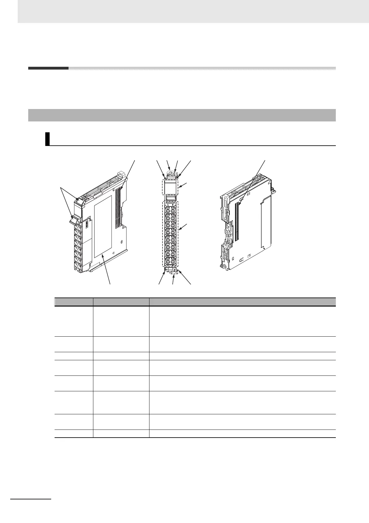
3-2-1 Parts and Names
NX-SIH400, NX-SID800, NX-SOD400, and NX-SOH200
Letter Name Function
A Marker attachment
locations
The locations where markers are attached. The markers made by
OMRON are installed for the factory setting. Commercially available mark-
ers can also be installed. For details, refer to 5-1-2 Attaching Markers on
page 5-4.
B NX bus connector This is the NX-series bus connector. Connect this connector to another
Unit, such as the NX-series Safety CPU Unit or a Safety I/O Unit.
D Unit hookup guides These guides are used to connect two Units.
C DIN Track mounting
hooks
These hooks are used to mount the NX Unit to a DIN Track.
E Protrusions for
removing the Unit
The protrusions to hold when removing the Unit.
F Indicators The indicators show the current operating status of the NX Unit or signal
I/O status. Refer to 3-2-2 Indicators on page 3-9. The number of indicators
depends on the NX Unit.
G Terminal block The terminal block is used to connect to external devices. It connects the
safety outputs. The number of terminals depends on the NX Unit.
H Unit specifications The specifications of the NX Unit are given here.
(C)(D)
(H)
(G)
(F)
(C)
(A)
(E)
(C)(E)
(C)
(B)
(B)