3 Part Names and Functions
3 - 42
NX-series Safety Control Unit User’s Manual (Z930)
Precautions for Correct Use
• The number of connections per Unit is as follows:
When NX-SOD400 and NX-SI are used: 2 (1 connected in series × 2 series)
When NX-SOH200 and NX-SI are used: 1 (1 connected in series × 1 series)
• The total wiring length of cables (L4 + L5 + L6 + ... + Ln) that can be connected to one test
output is 100 m max.
• Set the input device to Mechanical Contact Type to set the NX-SI EDM connection termi-
nals.
• The total wiring length of cable that can be connected from the safety output terminal to the
output device (L1 + L2 + L3) is 30 m max.
• The 3G3MX2 Inverter can be used in a Safety Category 3 or lower or a PLd or lower applica-
tion. It cannot be used in a Safety Category 4 or PLe application.
• Refer to the Multi-function Compact Inverter 3G3MX2-V1 User’s Manual (Cat. No. I585) for
the safety function settings and application precautions for a 3G3MX2 Inverter.
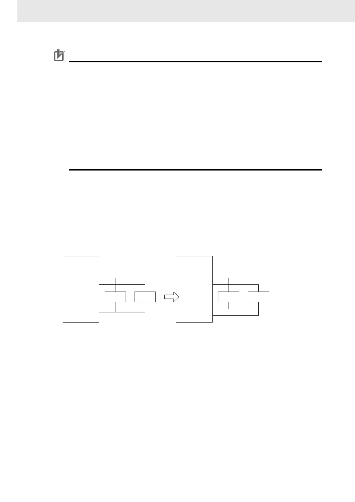
Connecting More Than One Output Device
The IOG terminals on the Safety Output Unit are connected internally in the Unit. Make sure that the
current that flows through each IOG terminal is less than the current capacity of the I/O power sup-
ply terminals. If the wiring is shared for the IOG lines to the output devices, the sum of the output
currents will flow in the IOG line. Therefore, wire the IOG lines separately.
NX-SO
So0
So1
IOG
IOG
NX-SO
So0
So1
IOG
IOG
LL LL
NG OK