5 Installation and Wiring
5 - 22
NX-series Safety Control Unit User’s Manual (Z930)
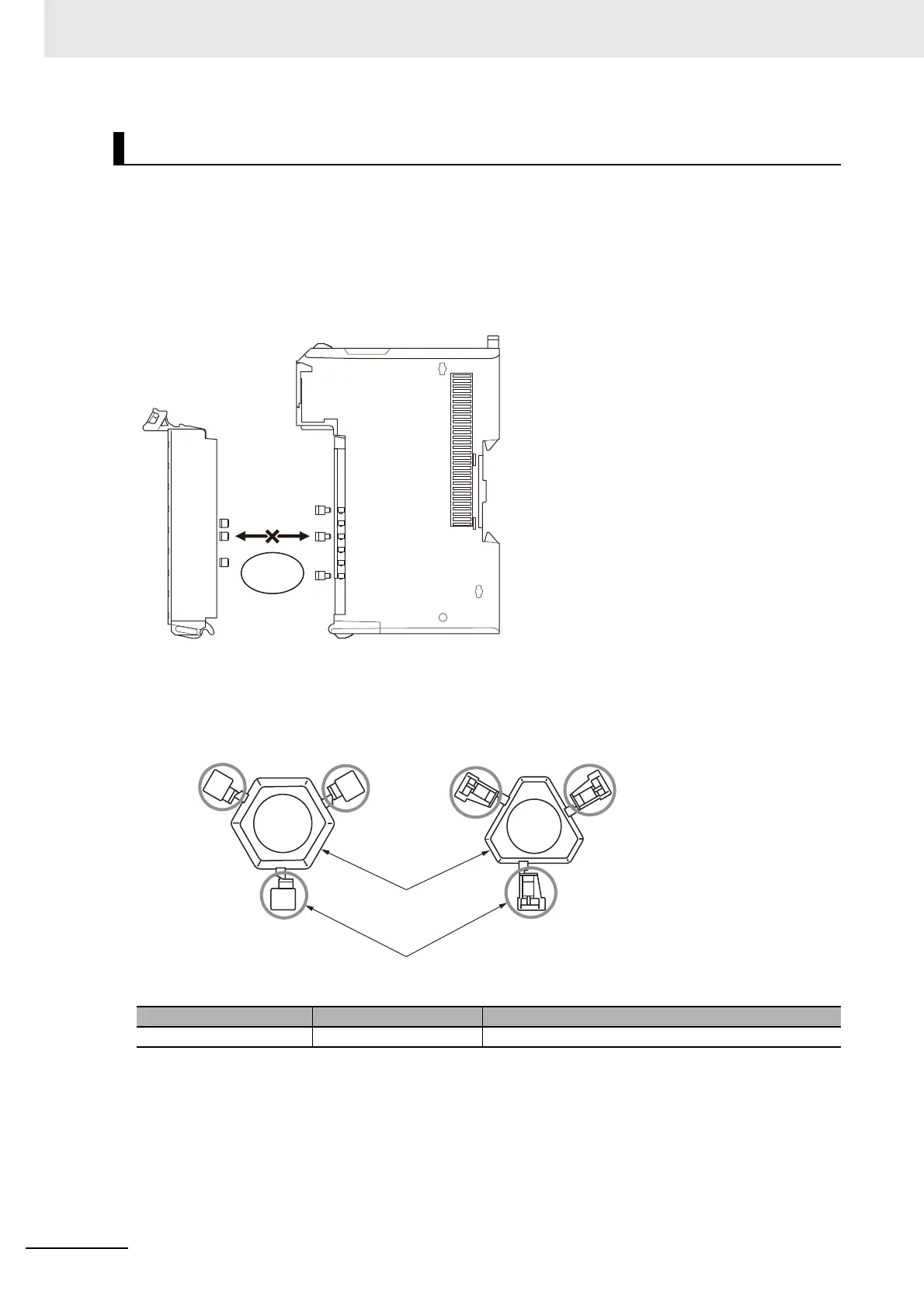
In order to prevent unintentionally installing the wrong terminal block, you can limit the combination of a
Unit and a terminal block.
Insert three Coding Pins (NX-AUX02) into three of the six incorrect attachment prevention holes on the
Unit and on the terminal block. Insert these pins into positions so that they do not interfere with each
other when the Unit and terminal block are connected to each other. You can use these pins to create
combinations in which the wrong terminal block cannot be attached because the pin patterns do not
match.
Types of Coding Pins
There are two types of Coding Pins, both with their own unique shape: one for terminal blocks and
one for Units. Three pins come with each runner.
Use the following Coding Pins.
Preventing Incorrect Attachment of Terminal Blocks
Name Model Specification
Coding Pin NX-AUX02 For 10 Units (Terminal Block: 30 pins, Unit: 30 pins)
Terminal block
Unit
Terminal block
cannot be attached.
For Terminal Block
For Unit
Coding Pins (Use this part.)
Runners