6 System Configuration and Setup
6 - 16
NX-series Safety Control Unit User’s Manual (Z930)
If the I/O terminals on the Safety I/O Unit are set to Dual Channel Mode, the device variable
can only be assigned to an even-numbered terminal.
The I/O ports for Safety I/O Units that are displayed in the I/O Map of the Safety CPU Unit are
described in this section.
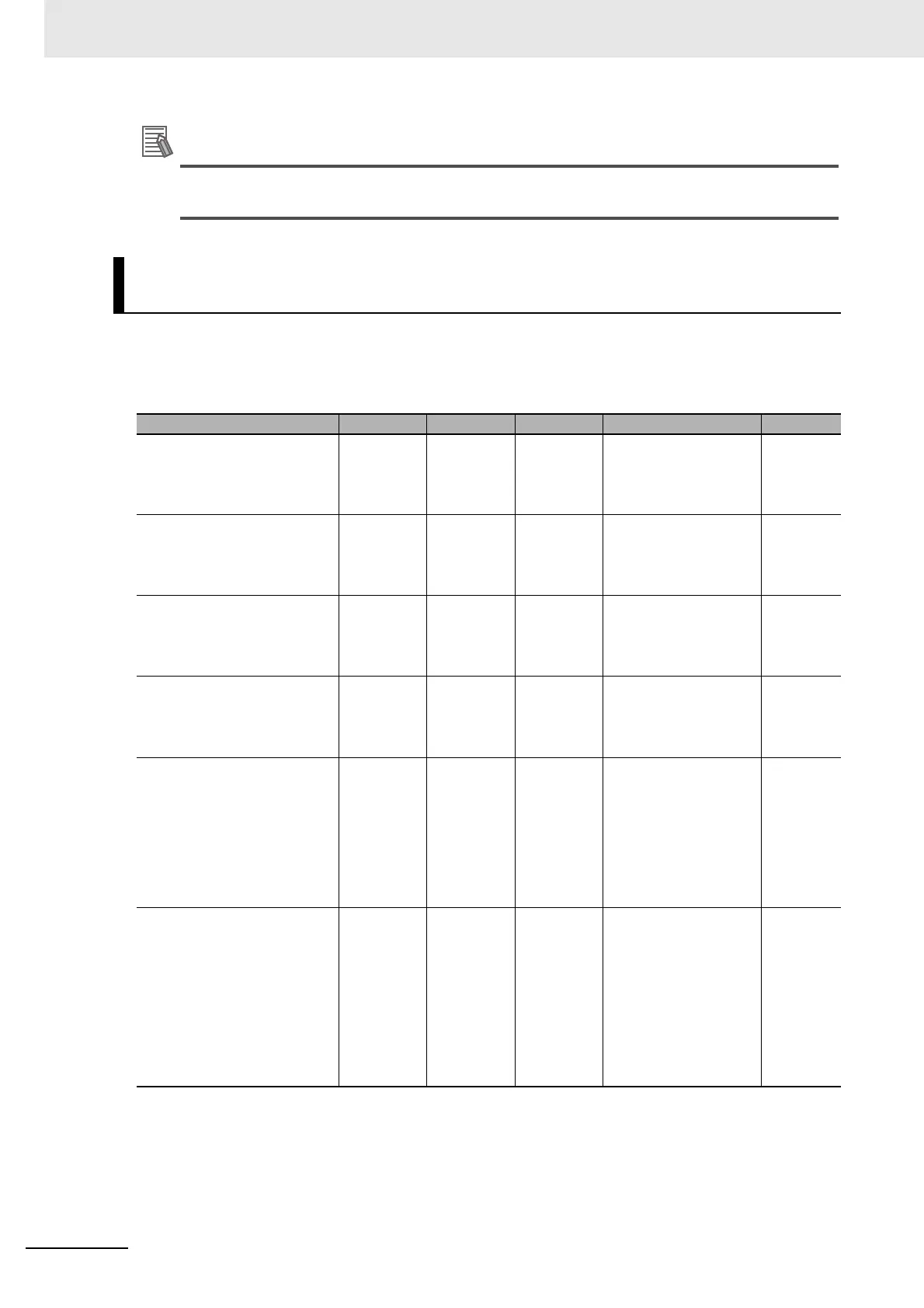
NX-SIH400 Safety Input Unit
I/O Ports for Safety I/O Units That Are Displayed in the I/O Map of the
Safety CPU Unit
Port Data type R/W Name Description Default
Si00 Logical Value SAFEBOOL R Si00 Logi-
cal Value
Gives the status of
safety input terminal
Si00.
0: OFF, 1: ON
0
Si01 Logical Value SAFEBOOL R Si01 Logi-
cal Value
Gives the status of
safety input terminal
Si01.
0: OFF, 1: ON
0
Si02 Logical Value SAFEBOOL R Si02 Logi-
cal Value
Gives the status of
safety input terminal
Si02.
0: OFF, 1: ON
0
Si03 Logical Value SAFEBOOL R Si03 Logi-
cal Value
Gives the status of
safety input terminal
Si03.
0: OFF, 1: ON
0
Safety Connection Status SAFEBOOL R Safety Con-
nection Sta-
tus
This flag indicates
when a safety connec-
tion is active. Use it for
an input to the Activate
terminal on a safety FB
or for safety connec-
tion/disconnection
applications.
0
Safety Input Terminal Status SAFEBOOL R Safety Input
Terminal
Status
This flag indicates the
status of the safety
input terminals.
0: An error has
occurred on one of the
safety input terminals.
1: All of the safety input
terminals are normal
(no errors).
0