9 Motion Control Functions
9-74
NJ/NX-series CPU Unit Motion Control User’s Manual (W507)
The output torque is limited by enabling and disabling the torque limit function of the Servo Drive and by
setting the torque limit value.
Different limits can be specified for the positive torque limit and negative torque limit.
For details, refer to the MC_SetTorqueLimit instruction in the NJ/NX-series Motion Control Instructions
Reference Manual (Cat. No. W508).
Precautions for Correct UsePrecautions for Correct Use
You cannot use the torque limit function for an NX-series Pulse Output Unit.
Latching is used to control positioning based on the position where a trigger signal occurs, such as a
signal from a sensor input. The position of the axis is recorded (i.e., latched) when the trigger signal
occurs. You can set up to two trigger signals for each axis. Use the MC_TouchProbe (Enable External
Latch) instruction to specify the Trigger Input Condition variable, Window Only variable, and Stopping
Mode Selection variable for the axis you want to latch. In addition to signals that connect to the Servo
Drive, you can also specify variables in the user program to use as a trigger. Use the MC_AbortTrigger
(Disable External Latch) instruction to abort latching. You can use latching only with a Servo Drive that
support latching (touch probe), such as the OMRON G5-series Servo Drives, or a GX-EC0211/EC0241
Encoder Input Terminal.
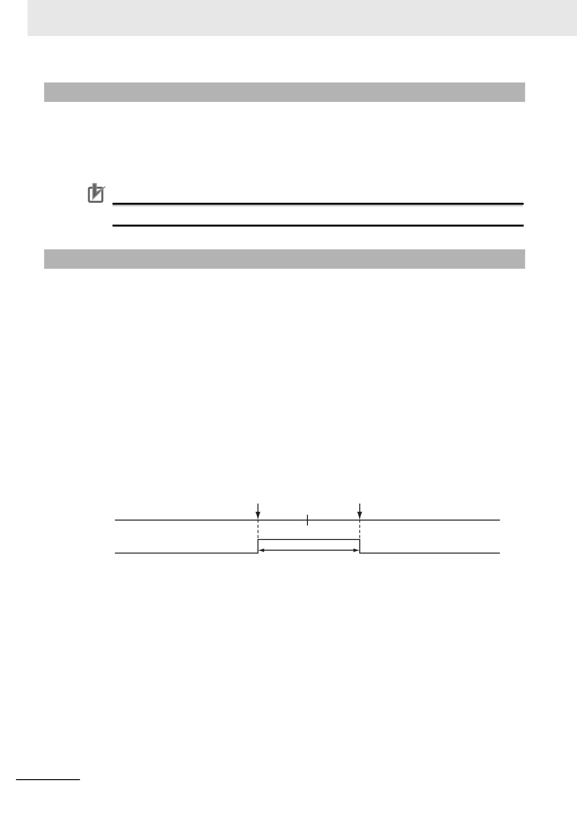
Use WindowOnly to detect only trigger signals within a specific start point and end point. The following
chart shows the ranges for different Count Modes.
Linear Mode
• The FirstPosition must be less than or equal to the LastPosition.
• An instruction error will occur if the FirstPosition is greater than the LastPosition.
• An instruction error will occur if a position beyond the position range of Linear Mode is specified.
9-8-2 Torque Limit
9-8-3 Latching
0x8000000000 0 0x7FFFFFFFFF
Latch enabled range
Window
LastPositionFirstPosition

 Loading...


