10 Sample Programming
10-46
NJ/NX-series CPU Unit Motion Control User’s Manual (W507)
To change from one cam table to another, two instances of the MC_CamIn (Start Cam Operation) instruction with
the same instance name are used. A different output parameter is assigned to the InCam (Cam Motion) output vari-
able from each instance. An error will occur if you assign the same output parameter. In this sample, a JMP (Jump)
instruction is used so that both instances are not executed at the same time.
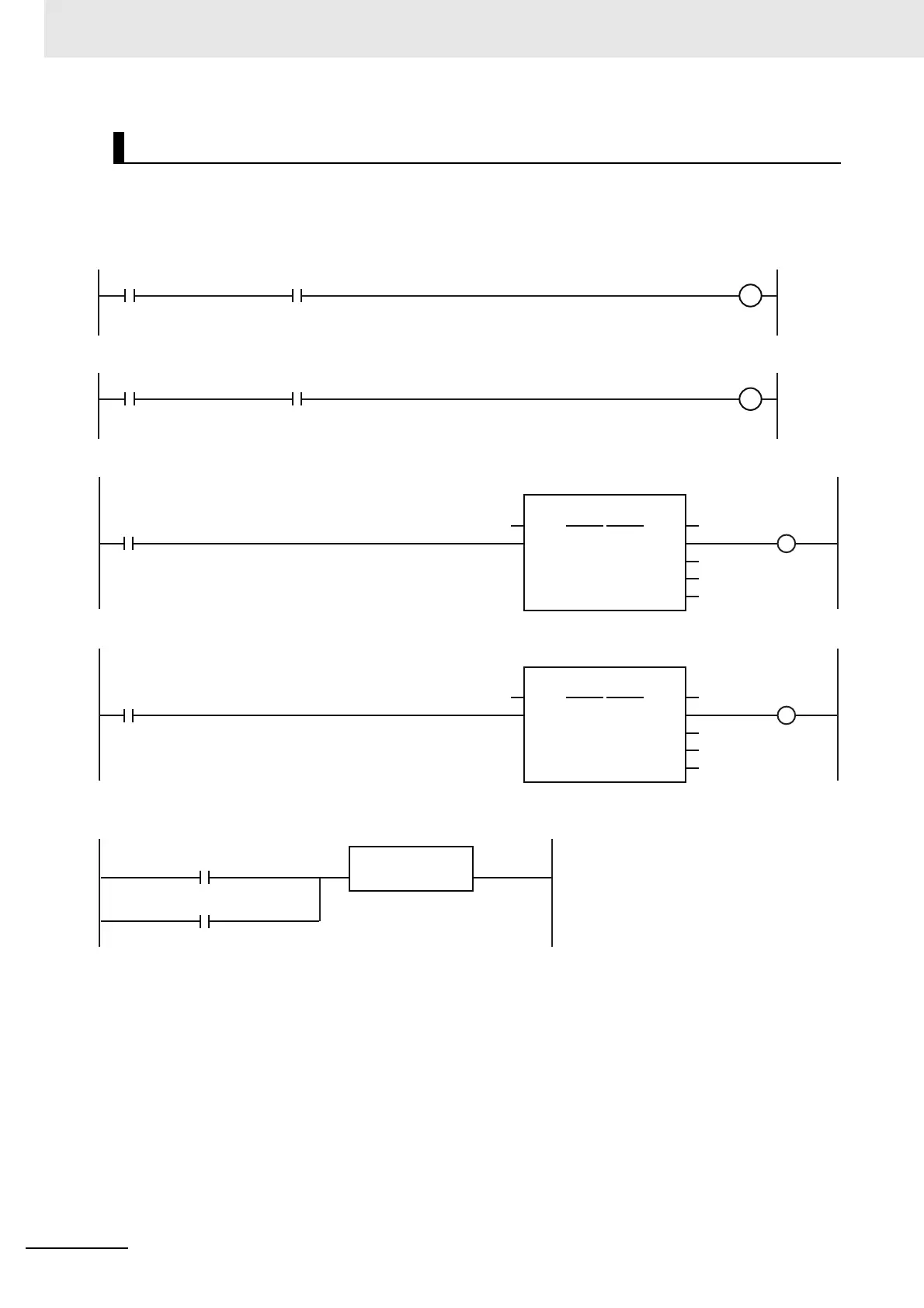
Ladder Diagram
StartPg
Lock0
MC_Axis000.DrvStatus.Ready
StartPg
Lock1
MC_Axis001.DrvStatus.Ready
Pwr1_Status
Lock0
Lock1
Enable Status
ErrorID
PWR1
Error
MC_Power
Axis Axis
Busy
MC_Axis000
Pwr1_Bsy
Pwr1_Err
Pwr1_ErrID
Pwr2_Status
Enable Status
ErrorID
PWR2
Error
MC_Power
Axis Axis
Busy
MC_Axis001
Pwr2_Bsy
Pwr2_Err
Pwr2_ErrID
MC_Axis000.MFaultLvl.Active
EN
FaultHandler
FaultHandler
MC_Axis001.MFaultLvl.Active
If a minor fault level error occurs for axis 0 or axis 1, the error handler for the device (FaultHandler) is executed.
Program the FaultHandler according to the device.
If the Servo Drive for axis 0 is ready, turn ON the Servo for axis 0.
If the Servo Drive for axis 1 is ready, turn ON the Servo for axis 1.
Check if the Servo Drive for axis 1 is ready when StartPg is TRUE.
Check if the Servo Drive for axis 0 is ready when StartPg is TRUE.

 Loading...


