2-11
2 Motion Control Configuration and Principles
NJ/NX-series CPU Unit Motion Control User’s Manual (W507)
2-3 Motion Control Principles
2
2-3-1 CPU Unit Tasks
Operation of a Priority-16 Periodic Task
You can refresh I/O in the priority-16 periodic task.
* The CPU Unit will temporarily interrupt the execution of a task in order to execute a task with a higher execution
priority.
For a single task, the primary period, which is the task period for the primary periodic task, is the stan-
dard period for execution. In this case, the primary period is automatically used as the motion control
period. (It is also the same as the process data communications cycle for EtherCAT communications.)
The NX102 CPU Unit, NX1P2 CPU Unit, and NJ-series CPU Unit support only the single task control.
For multi-motion, two kinds of period, the primary period and the task period of priority-5 periodic task
are the standard periods for execution. In this case, the motion control takes two kinds of period, while
the process data communications cycle for EtherCAT communications automatically takes each of the
task periods.
Periodic task execution is synchronized with the primary period. Set the task period of a periodic task
as an integer multiple of the primary period.
For example, if the primary period is 1 ms, then you can set the task period of a priority-5 periodic task
to 2 ms and the task period of a priority-16 periodic task to 4 ms. In that case, the start of the period for
the primary periodic task and the priority-5 periodic task will match once every two primary periods.
Similarly, the start of the period for the primary periodic task and the priority-16 periodic task will match
once every four primary periods.
Refer to the NJ/NX-series CPU Unit Software User’s Manual (Cat. No. W501) for details on the task
period.
If two process data communications cycles need to be identified, the communications cycle for
the primary periodic task is called process data communications cycle 1, while the
communications cycle for the priority-5 periodic task is called process data communications
cycle 2.
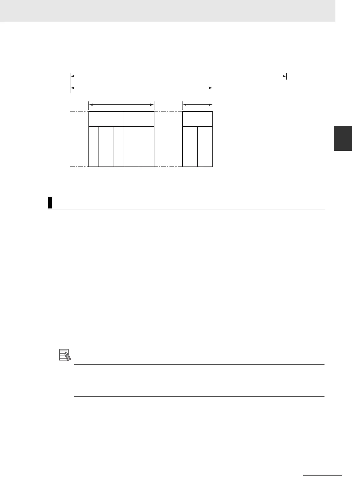
Task Period
**
Task processing time
Task execution time
Task period
I/O refresh
Task processing time
Control
processing
Control
processing
Output data processing
Refresh
executed.
Input data processing
System common
processing 1
User program
execution
System common
processing 2
User program
execution

 Loading...