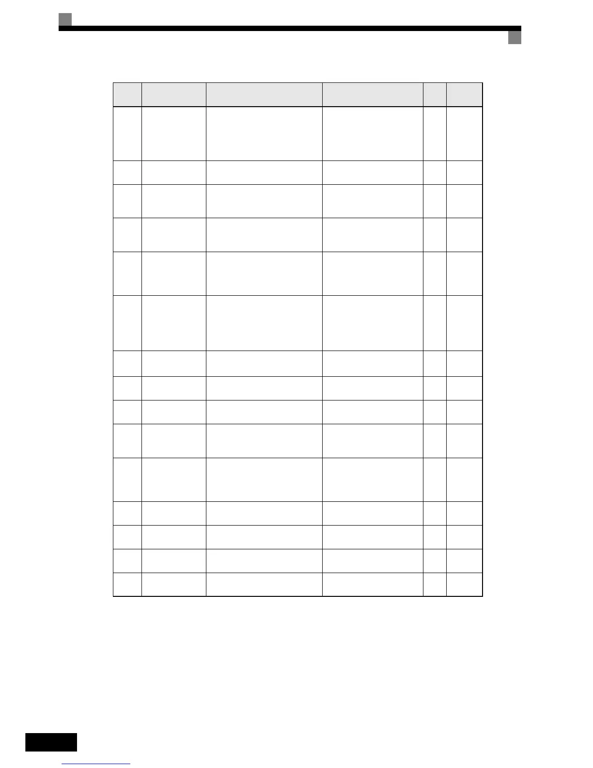
5-42
U1-13
Cumulative oper-
ation time
Monitors the total operating time
of the Inverter.
The initial value and the operat-
ing time/power ON time selection
can be set in o2-07 and o2-08.
(Cannot be output.)
1
hr.
4CH
U1-14
Software No.
(flash memory)
(Manufacturer’s ID number) (Cannot be output.) – 4DH
U1-15
Terminal A1
input level
Monitors the input level of analog
input A1. A value of 100% equals
10V input.
10 V: 100% 0.1% 4EH
U1-16
Terminal A2
input level
Monitors the input level of analog
input A2. A value of 100% equals
10V/20mA input.
10 V/20mA: 100% 0.1% 4FH
U1-18
Motor secondary
current (Iq)
Monitors the calculated value of
the motor secondary current.
The motor rated current corre-
sponds to 100%.
10 V:Motor rated current 0.1% 51H
U1-20
Output fre-
quency after soft-
starter (SFS out-
put)
Monitors the frequency reference
after the soft starter.
This frequency value does not
include compensations, such as
slip compensation.
*1
10 V: Max. frequency
0.01
Hz
53H
U1-24
PI feedback
value
*2
Monitors the feedback value
when PI control is used.
*3
10 V: 100% feedback value
0.01
%
57H
U1-28
Software No.
(CPU)
(CPU software No.) (Cannot be output.) – 5BH
U1-29 kWh display
Monitors the 4 lower digits, kWh
display.
(Cannot be output.)
1
kWh
5CH
U1-30 MWh display
Monitors the 5 higher digits,
MWh display.
(Cannot be output.)
0.1
MW
h
5DH
U1-31 LED Test
For testing LEDs on operator. If
this monitor is selected, all
LED’s light up (only on LED
operator).
(Cannot be output.) – 3CH
U1-34
OPE fault param-
eter
Shows the first parameter number
when an OPE fault is detected.
(Cannot be output.) – 61H
U1-36 PI input volume PI input volume 10 V: 100% PI input
0.01
%
63H
U1-37 PI output volume PI control output 10 V: 100% PI output
0.01
%
64H
U1-38
PI setpoint
*2
PI setpoint
*3
10 V: 100% PI setpoint
0.01
%
65H
Param-
eter
Number
Name Description
Output Signal Level During Multi-
Function Analog Output
Min.
Unit
MEMO-
BUS
Register