5-44
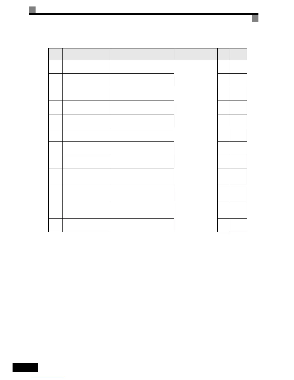
Fault Trace: U2
Note: The following errors are not included in the error trace: CPF00, 01, 02, 03, UV1, and UV2.
Param-
eter
Number
Name Description
Output Signal Level During
Multi-Function Analog Out-
put
Min.
Unit
MEMO-
BUS
Register
U2-01 Current fault The content of the current fault.
(Cannot be output.)
– 80H
U2-02 Last fault The error content of the last fault. – 81H
U2-03
Reference frequency at
fault
The reference frequency when the
last fault occurred.
0.01
Hz
82H
U2-04 Output frequency at fault
The output frequency when the last
fault occurred.
0.01
Hz
83H
U2-05 Output current at fault
The output current when the last fault
occurred.
0.01
A
84H
U2-07
Output voltage reference at
fault
The output reference voltage when
the last fault occurred.
0.1
V
86H
U2-08 DC bus voltage at fault
The DC bus voltage when the last
fault occurred.
1 V 87H
U2-09 Output power at fault
The output power when the last fault
occurred.
0.1
kW
88H
U2-11
Input terminal status at
fault
The input terminal status when the
last fault occurred.
The format is the same as for U1-10.
–8AH
U2-12
Output terminal status at
fault
The output terminal status when the
last fault occurred. The format is the
same as for U1-11.
–8BH
U2-13 Operation status at fault
The operating status when the last
fault occurred. The format is the same
as for U1-12.
–8CH
U2-14
Cumulative operation time
at fault
The operating time when the last fault
occurred.
1
hr.
8DH