5-48
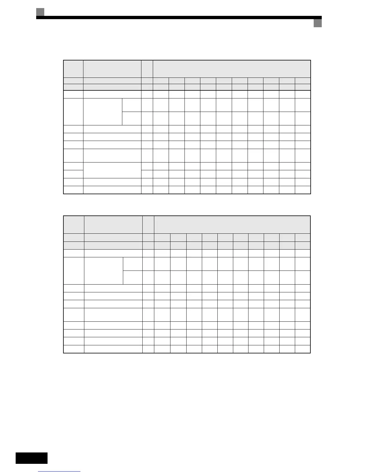
400 V Class Inverters in Protection Class IP00 and NEMA 1 / IP20
Param-
eter
Number
Name Unit Factory Setting
– Inverter Capacity kW 0.4 0.75 1.5 2.2 3.7 4.0 5.5 7.5 11 15
o2-04 kVA selection – 20 21 22 23 24 25 26 27 28 29
b8-04 Energy-saving coefficient – 576.40 447.40 338.80 313.60 245.80 236.44 189.50 145.38 140.88 126.26
C6-02
Carrier frequency
selection
*1
*1. The initial settings for C6-02 are as follows: 2: 5.0 kHz, 3: 8.0 kHz, 4: 10 kHz, 5: 12.5 kHz, and 6: 15 kHz. If the carrier frequency is set higher than
the factory setting for Inverters with outputs of 30 kW or more, the Inverter rated current will need to be reduced.
Normal
Duty 1
–6666666666
Normal
Duty 2
–6666666634
E2-01 Motor rated current A 1.00 1.60 3.10 4.20 7.00 7.00 9.80 13.30 19.9 26.5
E2-03 Motor no-load current A 0.60 0.80 1.40 1.50 2.30 2.30 2.60 4.00 5.6 7.6
E2-05 Motor line-to-line resistance W 38.198 22.459 10.100 6.495 3.333 3.333 1.595 1.152 0.922 0.550
L2-02
Momentary power loss ride
through time
sec. 0.1 0.1 0.2 0.3 0.5 0.5 0.8 0.8 1.0 2.0
L2-03
Min. baseblock (BB) time
Voltage recovery time
sec. 0.1 0.2 0.3 0.4 0.5 0.6 0.6 0.7 0.8 0.9
L2-04 sec. 0.3 0.3 0.3 0.3 0.3 0.3 0.3 0.3 0.3 0.3
L8-02 Overheat pre-alarm level °C95959595959595959595
L8-06 Input phase loss detection % 5.0 7.5 10.0 10.0 12.0 10.0 10.0 20.0 23.0 17.0
Parame-
ter Num-
ber
Name Unit Factory Setting
– Inverter Capacity kW 18.5 22 30 37 45 55 75 90 110 132
o2-04 kVA selection – 2A 2B 2C 2D 2E 2F 30 31 32 33
b8-04 Energy-saving coefficient – 115.74 103.58 92.54 76.32 71.56 67.20 46.20 41.22 36.23 33.18
C6-02
Carrier frequency
selection
*1
*1. The initial settings for C6-02 are as follows: 2: 5.0 kHz, 3: 8.0 kHz, 4: 10 kHz, 5: 12.5 kHz, and 6: 15 kHz. If the carrier frequency is set higher than
the factory setting for Inverters with outputs of 30 kW or more, the Inverter rated current will need to be reduced.
Normal
Duty 1
–6 644443332
Normal
Duty 2
–4 433322322
E2-01 Motor rated current A 32.9 38.6 52.3 65.6 79.7 95.0 130.0 156.0 190.0 223.0
E2-03 Motor no-load current A 7.8 9.2 10.9 19.1 22.0 24.0 36.0 40.0 49.0 58.0
E2-05 Motor line-to-line resistance W 0.403 0.316 0.269 0.155 0.122 0.088 0.092 0.056 0.046 0.035
L2-02
Momentary power loss ride
through time
sec.2.0 2.02.02.02.02.02.02.02.02.0
L2-03 Min. baseblock (BB) time sec. 1.0 1.0 1.1 1.1 1.2 1.2 1.3 1.5 1.7 1.7
L2-04 Voltage recovery time sec. 0.6 0.6 0.6 0.6 0.6 1.0 1.0 1.0 1.0 1.0
L8-02 Overheat pre-alarm level °C 95 95 95 95 95 100 95 110 110 110
L8-06 Input phase loss detection % 17.0 20.0 20.0 20.0 20.0 20.0 20.0 16.0 16.0 16.0