6-78
Monitor Data
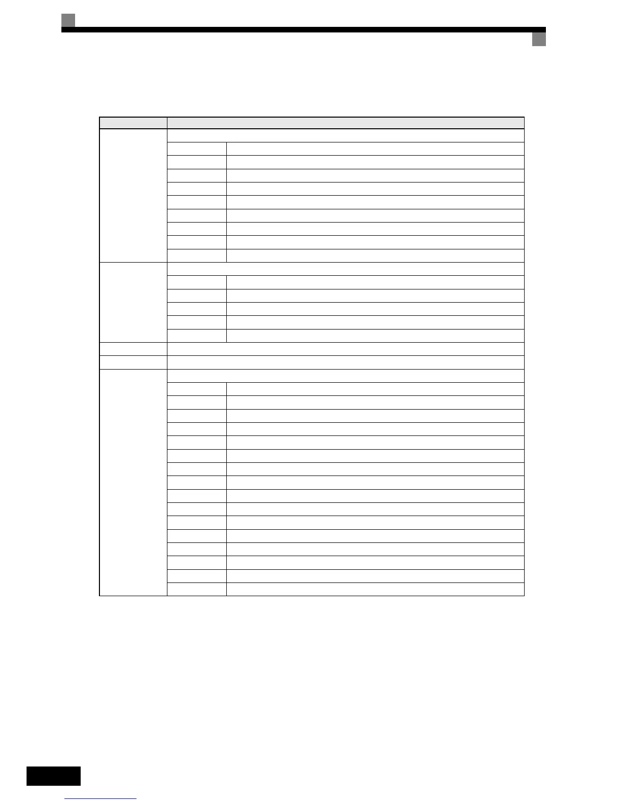
The following table shows the monitor data. Monitor data can only be read.
Register No. Contents
0010H
Inverter status signal
Bit 0 During run
Bit 1 Zero speed
Bit 2 During reverse operation
Bit 3 Reset signal active
Bit 4 During speed agree
Bit 5 Inverter ready
Bit 6 Minor fault
Bit 7 Major fault
Bits 8 to F Not used
0011H
Operator status
Bit 0 During OPE alarm
Bit 1 During fault
Bit 2 Operator in programming mode
Bit 3, 4 00: JVOP-160 attached, 01: JVOP-161 attached, 11: PC connected
Bit 5 to F Not used
0012H OPE Fault Number
0013H Not used
0014H
Fault Content 1
Bit 0 PUF, DC bus fuse blown
Bit 1 UV1
Bit 2 UV2
Bit 3 UV3
Bit 4 Not used
Bit 5 GF, Ground fault
Bit 6 OC, Over current
Bit 7 OV, DC bus over voltage
Bit 8 OH, Inverter heatsink overheat pre-alarm
Bit 9 OH1, Inverter heatsink overheat
Bit A OL1, Motor overload
Bit B OL2, Inverter overload
Bit C OL3, Overload detection
Bit D Not used
Bit E Not used
Bit F Not used