Protective and Diagnostic Functions
7-3
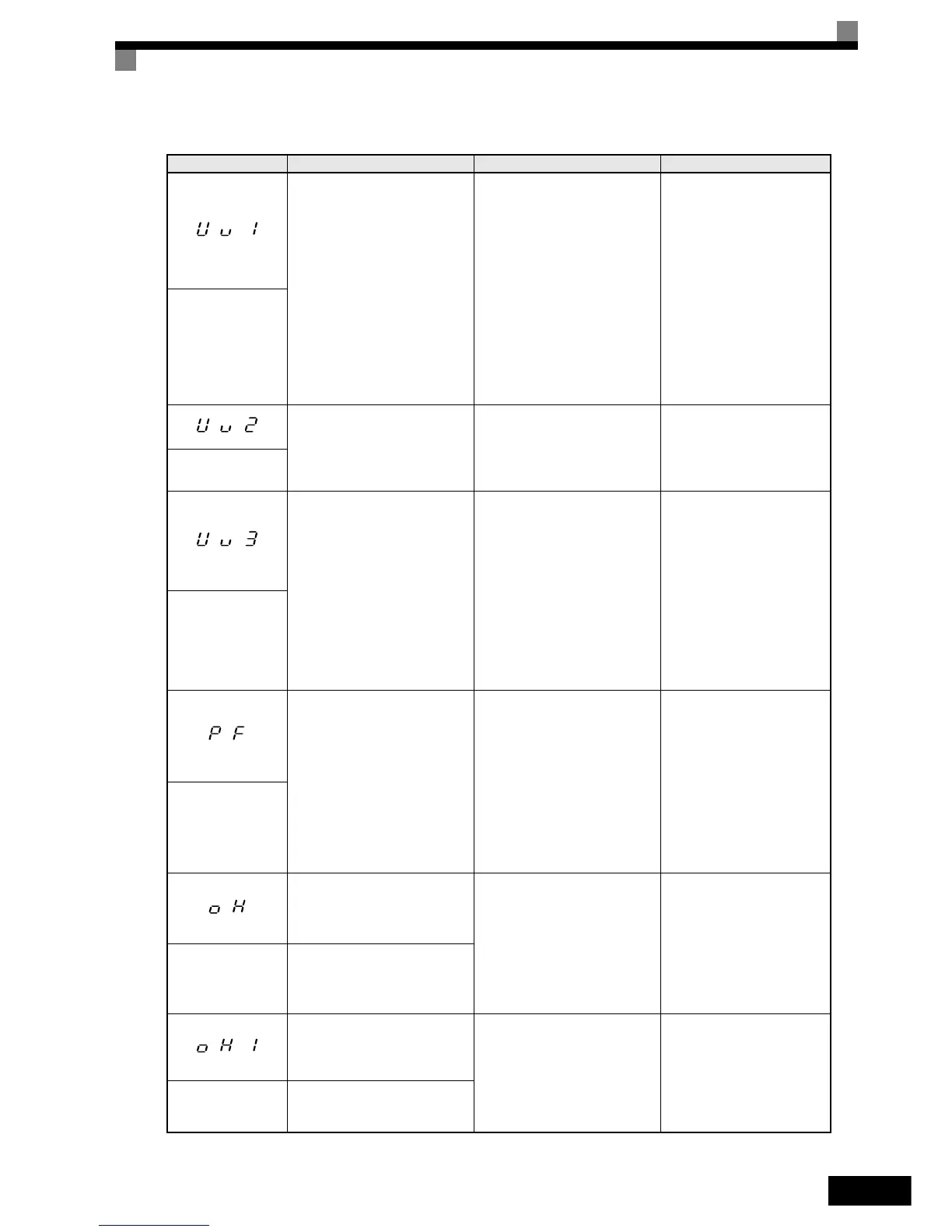
DC Bus Undervoltage
The DC bus voltage is below the
Undervoltage Detection Level
(L2-05). The default settings are:
200 V class: 190 VDC
400V class: 380VDC
Main Circuit MC Operation
Failure
The MC stopped responding dur-
ing Inverter operation. (Applica-
ble Inverter Capacities
200 V class: 37 to 110 kW
400 V class: 75 to 300 kW)
• The voltage fluctuations of the
power supply are too high.
• A momentary power loss has
occurred.
• The terminal screws of the
input power supply are loose.
• An open-phase error occurred
at the input terminals.
• The acceleration time is set too
short.
• A fault occurred in the inrush
current prevention circuit.
• Check the input voltage.
• Check the wiring of the
input terminals.
• Increase the accel time set-
tings C1-01/03.
• In case of Main Circuit MC
Operation Failure replace
the Inverter.
UV1
DC Bus Undervolt
Control Power Supply
Undervoltage
Undervoltage of the control cir-
cuit while the Inverter was run-
ning.
An external load at the control
terminals was pulling down the
Inverter’s power supplies or there
was an internal short in the
power/gate drive board.
• Remove all connections to
the control terminals and
cycle the power to the
Inverter.
• Replace the Inverter.
UV2
CTL PS Undervolt
Inrush Current Prevention Circuit
Fault
An overheating of the charging
resistor for the DC bus capacitors
occurred.
The MC of the charging circuit
did not respond 10 sec. after the
MC ON signal has been output.
(Applicable Inverter Capacities:
200 V class: 37 to 110 kW
400 V class: 75 to 300 kW)
The contactor of the inrush cur-
rent prevention circuit is defec-
tive.
• Cycle the power to the
Inverter.
• Replace the Inverter
UV3
MC Answerback
Main Circuit Voltage Fault
An unusual big ripple on the DC
bus voltage has been detected.
Only detected when L8-05=1, the
detection level is set by L8-06
(refer to
page 6-48)
• An open-phase occurred in the
input power supply.
• A momentary power loss
occurred.
• The wiring terminals for the
input power supply are loose.
• The voltage fluctuations in the
input power supply are too
high.
• The voltage balance between
the phases is bad.
• Tighten the input terminal
screws
• Replace the Inverter
PF
Input Phase Loss
Heatsink Overheat
The temperature of the Inverter's
cooling fin exceeded the setting
in L8-02 while L8-03 = 0 to 2.
• The ambient temperature is too
high.
• There is a heat source nearby.
• The Inverter's cooling fan(s)
stopped.
• The Inverter's internal cooling
fan has stopped and L8-32=1
• Check for dirt build-up on
the fans or heatsink.
• Install a cooling unit.
• Remove the heat source.
• Replace the cooling fan(s)
Inverter's Cooling Fan Stopped
OH
Heatsink Overtemp
Heatsink Overheat
The temperature of the Inverter’s
heatsink exceeded 105 °C
• The ambient temperature is too
high.
• There is a heat source nearby.
• The Inverter's cooling fan(s)
stopped.
• The Inverter's internal cooling
fan has stopped.and L8-32=1
• Check for dirt build-up on
the fans or heatsink.
• Install a cooling unit.
• Remove the heat source.
• Replace the cooling fan(s)
OH1
Heatsnk MAX Temp
Inverter’s Cooling Fan Stopped
Table 7.1 Fault Detection
Display Meaning Probable Causes Corrective Actions