7-10
(flashing)
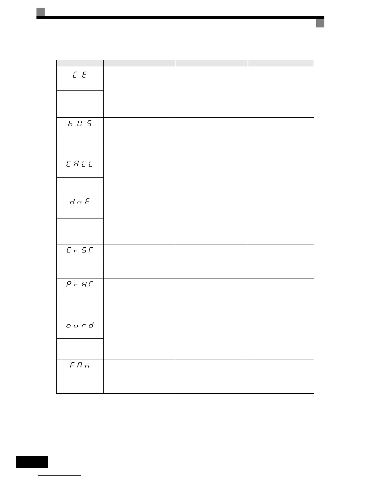
MEMOBUS Communications
Alarm
Detected when control data was
not received correctly for 2 sec-
onds and H5-04=4 and H5-05=1.
Connection is broken and/or the
master has stopped the communi-
cation.
Check the connections and all
user-side software configura-
tions.
CE
MEMOBUS Com
Err
(flashing)
(flashing)
Option Card Communications
Alarm
After initial communication was
established, the connection was
lost.
Connection is broken and/or the
master has stopped the communi-
cation.
Check the connections and all
user-side software configura-
tions.
BUS
Option Com Err
(flashing)
(flashing)
Communication on Standby
Communication has not yet been
established.
Connection was not made prop-
erly or user software was not con-
figured to the proper baud rate or
configuration (e.g. Parity)
Check the connections and all
user-side software configura-
tions.
CALL
ComCall
(flashing)
Drive not Enabled
Detected when a multi-function
digital input (H1-01 to H1-05) is
programmed for 6A or 70.
The Inverter does not have the
enable command when the RUN
command is applied.
This alarm decelerates the motor.
• Enable command was lost
while the Inverter was running.
• The RUN command was
applied prior to the enable sig-
nal.
• Check the wiring and
sequence of the external
signals.
• Apply and maintain the
enable command before
applying the RUN signal
DNE
Drive not Enable
(flashing)
(flashing)
Detected when a RESET com-
mand is input while the RUN
command is still active.
The RUN command has not been
removed and a RESET command
is input by digital input or by the
RESET button on the Digital
Operator.
Remove the RUN signal first
and reset the fault.
Ext Run active
Cannot Reset
(flashing)
Motor is preheating.
One of the digital inputs (H1-01
to H1-05) is programmed to 60 or
80 and the input is switched ON.
• Check the wiring and
sequence of the external
signals.
• Check the parameter set-
tings.
PRHT
Motor Preheating
(flashing)
(flashing)
Emergency Override is active
On of the digital inputs (H1-01 to
H1-05) is programmed to 81 or
82 and the input is switched ON
• Check the wiring and
sequence of the external
signals.
• Check the parameter set-
tings.
OVRD
Emergcy Override
(flashing)
(flashing)
Internal Cooling Fan Alarm
The Inverter’s internal cooling
fan failed while L8-32=0
The Inverter’ internal cooling fan
failed or is blocked.
• Check the internal cooling
and clean it in case it is
dirty.
• Replace the cooling fan or
the Inverter.
FAN
Cooling FAN Err
Table 7.2 Alarm Content
Display Meaning Probable Causes Corrective Actions