Wiring Main Circuit Terminals
2-23
Ground Wiring
Observe the following precautions when wiring the ground line.
• Always use the ground terminal of the 200 V Inverter with a ground resistance of less than 100 Ω and that
of the 400 V Inverter with a ground resistance of less than 10 Ω.
• Do not share the ground wire with other devices, such as welding machines or power tools.
• Always use a ground wire that complies with technical standards on electrical equipment and minimize the
length of the ground wire.
Leakage current flows through the Inverter. Therefore, if the distance between the ground electrode and
the ground terminal is too long, potential on the ground terminal of the Inverter will become unstable.
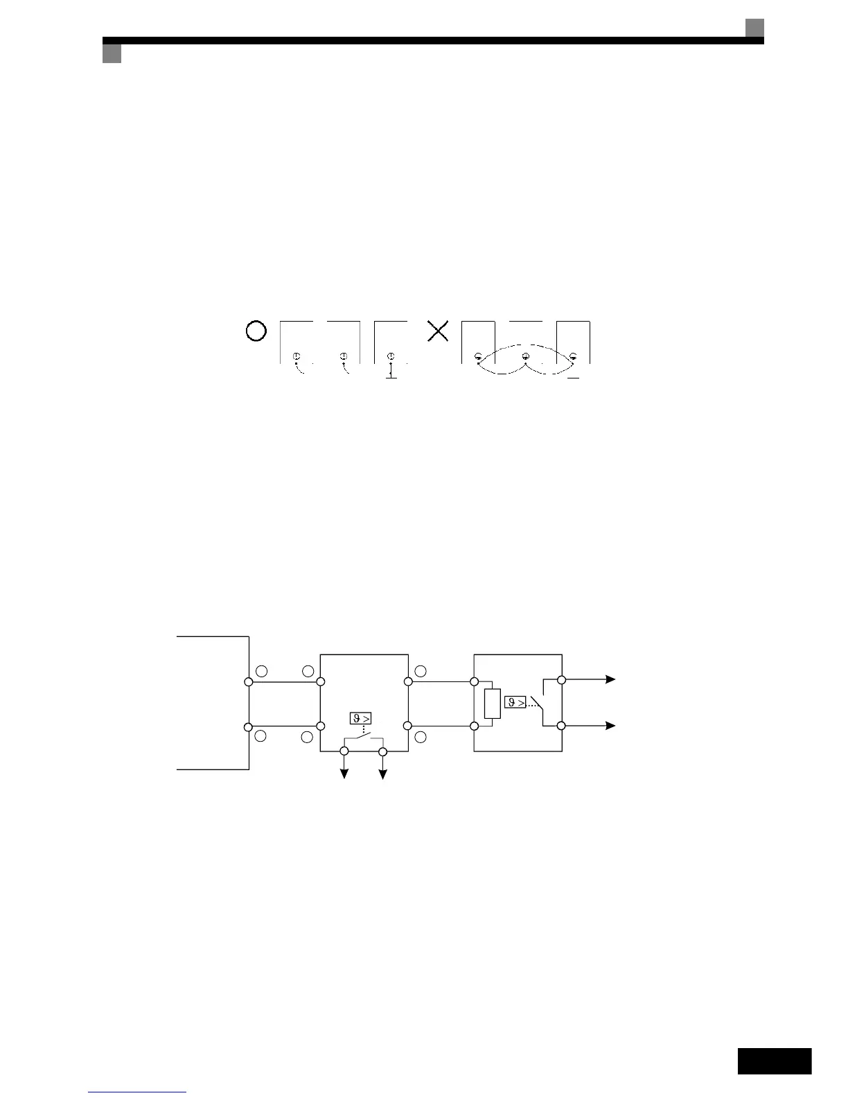
• When using more than one Inverter, be careful not to loop the ground wire.
Fig 2.9 Ground Wiring
Connecting a Braking Unit (CDBR) and a Braking Resistor Unit (LKEB)
Connect a Braking Unit and a Braking Resistor Unit to the Inverter as shown in the Fig 2.10.
The Braking Resistor Unit will not work if L3-04 is set to 1 (i.e., if stall prevention is enabled for decelera-
tion). Hence the deceleration time may be longer than the set time (C1-02/04).
To prevent the braking unit/braking resistor unit from overheating, design the control circuit to turn OFF the
inverter output using the thermal overload relay of the Unit as shown in Fig 2.10.
Fig 2.10 Connecting the Braking Resistor Unit and Braking Unit
OK
NO
Thermal Overload
Relay Contact
Thermal
Overload
Relay Contact
-
+
-
+
3
+
3
-
0
Inverter
CDBR
Braking Unit
Braking Resistor