2-24
Connecting Braking Units in Parallel
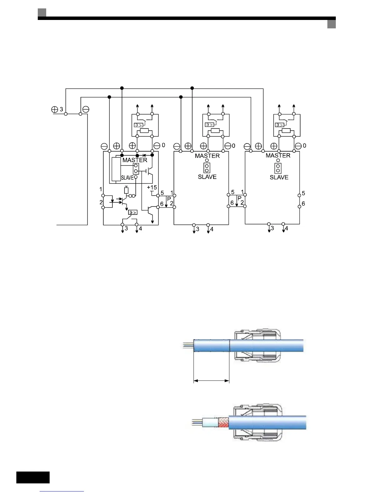
When connecting two or more Braking Units in parallel, use the wiring and jumper settings like shown in Fig
2.11. There is a jumper for selecting whether each Braking Unit is to be a master or slave. Select “Master” for
the first Braking Unit only, and select “Slave” for all other Braking Units (i.e., from the second Unit onwards).
Fig 2.11 Connecting Braking Units in Parallel
Wiring the Power Cables of IP54 Inverters
Special attention has to be paid for wiring the motor cables of the IP54 inverters. The smaller capacities fea-
ture an EMC cable gland which is used to earth the motor cable shield easily.
Installing the Metal (EMC) Cable Gland on IP54 Inverters 7.5 to 30kW
1. With the Standard Contacting:
Thermal overload relay contact Thermal overload relay contact Thermal overload relay contact
Braking
Resistor
Unit
Braking
Resistor
Unit
Braking
Resistor
Unit
Inverter
Braking Unit #2 Braking Unit #3
Braking Unit #1
Thermal overload relay contact Thermal overload relay contact
Thermal overload relay contact
appr. 15 mm
Make a round cut into the outer sheath,
with a length of appr. 14mm from the end
of the sheath but do not remove the sheath.
Guide the cable through the gland.
Pull off the cut-off outer sheath, remove
some part of the shield and pull the cable
back until the shield has proper contact to
the springs of the cable gland.