range Pi 用户手册 深圳市迅龙软件有限公司版权所有
www.orangepi.cn 27 www.xunlong.tv
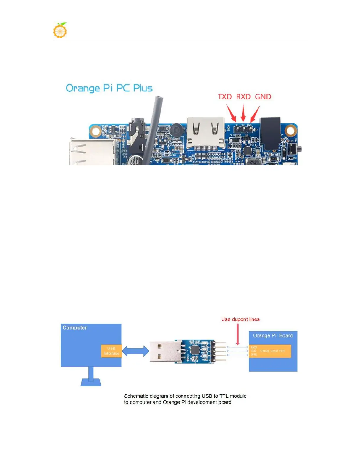
2) The corresponding relationship between the debug serial port GND, TXD and RXD
pins of the development board is shown in the figure below
3) The GND, TXD and RXD pins of the USB to TTL module need to be connected to
the debug serial port of the development board through a DuPont cable
a. Connect the GND of the USB to TTL module to the GND of the development
board
b. Connect the RXD of the USB to TTL module to the TXD of the development
board
c. Connect the TXD of the USB to TTL module to the RXD of the development
board
4) The schematic diagram of connecting the USB to TTL module to the computer and
the Orange Pi development board is shown below