Lever no: Valve function
2 Right support leg, rear Up / down
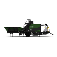
3 Feed hopper Up / down
4 Left support leg, front Up / down
5 Right support leg, front Up / down
6 Drawbar In / out
4.2.4 Leveling the machine
1. Ensure that the feed hopper is raised clear of the ground when leveling the machine. The feed hopper
may be lowered onto the ground only when the machine is properly leveled.
2. Operate the valves for the hydraulic jack stands until the machine is properly leveled (See section
4.2.2 "Lever/Controls overview")
3. Use the "spirit levels" on the frame during the leveling.
NOTE: The leveling of the compactor may change during time if the surface is not entirely solid. Therefore,
check the leveling regularly. Incorrect leveling may cause machine errors and uneven wear or damage to the
chamber belts.
4.2.5 Placing the tractor with telescopic drawbar
The tractor should be placed on the left side of the machine when connecting the PTO drive shaft. The drive
shaft should be horizontal and parallel to the input shaft on the gearbox. When disconnecting the drive
shaft from the power supply/tractor, the drive shaft must be secured to the machine without disconnecting
it from the input shaft. This is to avoid that the drive shaft falls off the machine during transport.
4.2.6 Power take off
The PTO drive shaft is delivered with its own user manual from the manufacturer. Assemble the shaft accord-
ingly. Maintain and lubricate the PTO-shaft according to instructions given in the PTO-manual. Power
requirement:
120hp / 90 kW (diesel engine)
90hp / 75 kW (electric motor)
IMPORTANT: If any dangerous situations occur, shut down the PTO right away.
4.2.7 PTO Speed
The machine is designed for a PTO speed of 850 rpm. Ensure that the PTO speed and rotational direction is
correct (counter clockwise rotation when viewed from the tractor is correct).
NOTE: It is important for the machine performance (the hydraulic system) that the PTO speed is steady.
4.2.8 Electrical power source
The machine is equipped with a 24V electrical power system, and is self-supplied through an integrated gen-
erator and a battery pack. The main power switch separates the battery pack from the rest of the system,
and must always be turned off whenever the machine is parked and during transportation.
4.2.9 Hydraulic connections
The machine has two separate hydraulic systems: The main system includes oil tank, pumps and valves, and
is powered by the PTO drive shaft via the gearbox. This system powers all functions used during baling and
are controlled either automatically or manually from the display unit.
The auxiliary system is connected to the tractors hydraulic system and is powered by this.
4 OPERATION 34