This is the most typical condition. These bushings are worn the most when the chamber is «full», and the
bale pressure forces the rollers outwards. Thus the most wear on the bushings will be on the outer side.
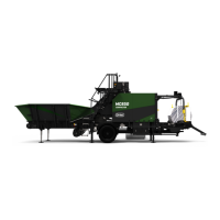
2. Drive chain
This condition occurs on the bushings that are affected by the drive chain direction. A turning point is shown
in Figure 7.26. The wear is also influenced by the chamber pressure. But not as excessive as for condition 1.
Thus the most wear in these conditions are located on the opposite side of the chain contact side.
Figure 7.26 :
Bushings
Inspection
Use a crowbar and inspect each bushing from multiple angles. The worn out areas might be located at dif-
ferent possitions according to how the machine has been used, and which material has been baled.
7.11.2 Permissible wear
Small type, 40 mm
New bearing: 40 mm inside diameter, 44mm outside diameter.
Defect bearing: ≥ 42,2 mm inside diameter.
Measure the diameter several places to get the correct impression of the bearing ovality.
Large type, 50 mm
New bearing: 50 mm inside diameter, 55 mm outside diameter
Defect bearing: ≥ 52,7 mm inside diameter.
Measure the diameter several places to get the correct impression of the bearing ovality. The material thick-
ness in bearings must under no circumstances be ≤ 0,2 mm. If so, the bearing is defect and must be
replaced immediately. The reason is to avoid serious damage to the rollers axle, and potential mechanical
breakdown.
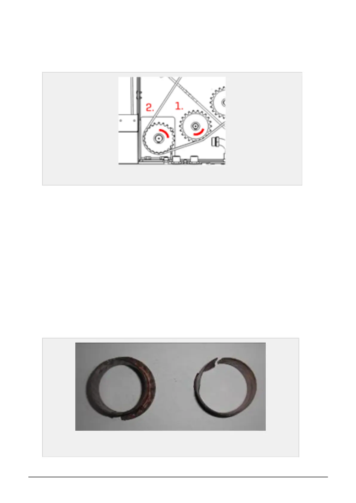
Figure 7.27 :
Example picture of plain bearing. New bearing to the left, and worn out/defect
bearing to the right.
7 MAINTENANCE AND MECHANICAL ADJUSTMENTS 70