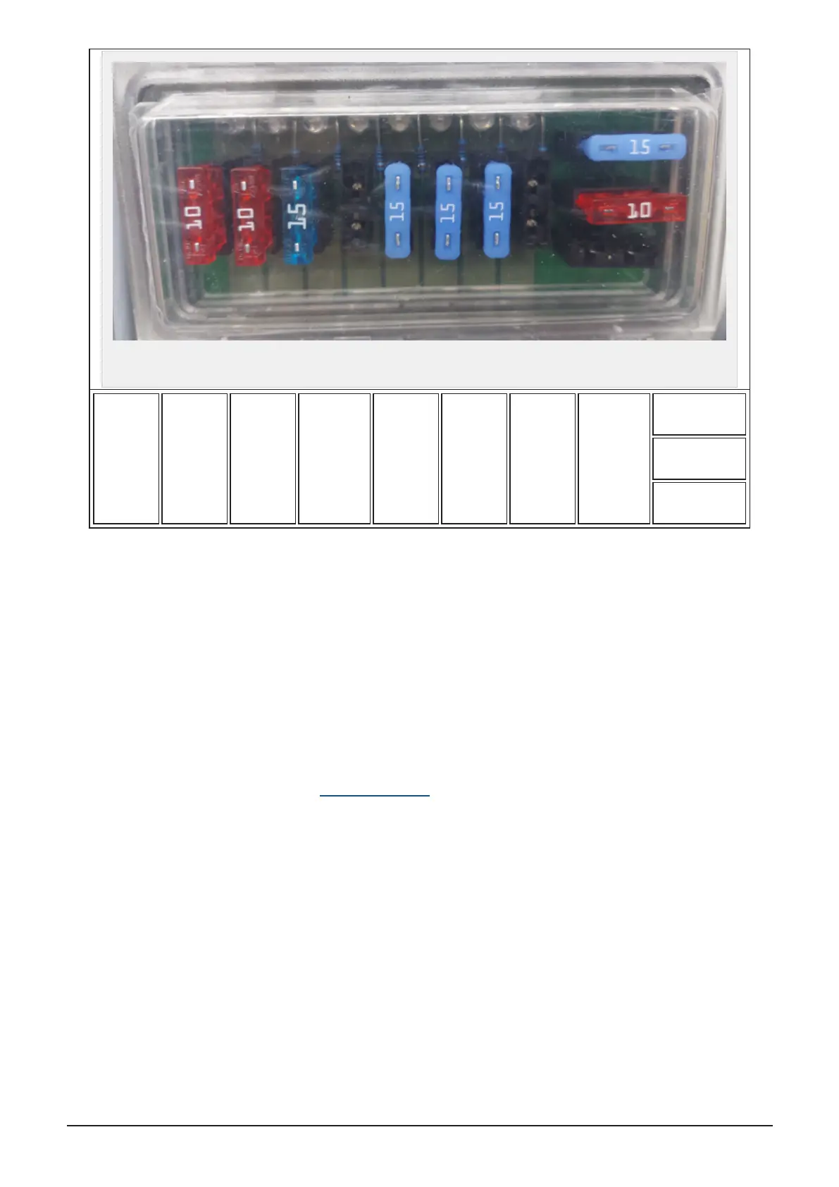
Figure 10.1 :
Fuse box
1
10A
2
10A
3
15A
Free
5
15A
6
15A
7
15A
Free
9
Spare
10
Spare
11
Spare
1. Terminal A og B (printed circuit board) 10A
2. Sensors 10A
3. Lubrication system 15A
4. Free 5A (Spare)
5. Hydraulic control V1 - V16 15A
6. Hydraulic control V17 - V32 15A
7. 15A
8. Free
9, 10 and 11. 10A, 15A og 20A (Spare)
10.5 SCHEMATICS
All schematics can be found online at www.orkel.com/qr for higher resolution.
10 ELECTRICS 92