18
COMBINER FIXED ON A HEAT-DISSIPATING SUPPORT
The laser head can be fixed to a flat base, provided that heat dissipation is effective through it. An
optical table or a milled baseplate typically meets these requirements.
Refer to chapter 7-5 for detailed drawings of the laser head. L-shaped flanges are provided with M6
screws to fix the combiner to a 1-inch or 25-mm pitch grid.
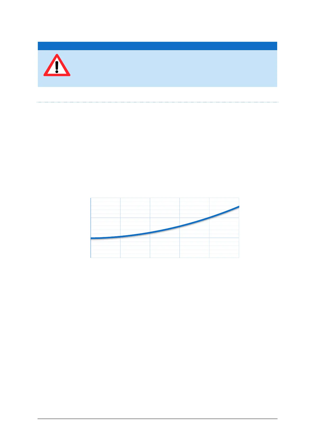
The amount of heat released is sharply increasing as the temperature of the laser head is itself
increasing. As an illustration, here is the electrical power consumed by a typical combiner against the
temperature of its base plate:
Figure 3-1: Power consumption of a typical L4Cc combiner (405nm, 488nm, 561nm, 640nm, total optical power:
400mW)
Noticeable features of this characteristic are:
- The maximum consumed power is reached as the base plate is at its hottest,
- The minimum consumed power is reached in a zone typically between 15°C and 25°C
For those reasons, the supporting medium must ensure a proper dissipation of the generated heat. This is
the purpose of the standard heatsinks described in the previous paragraph.
The following figure can guide you when selecting a heatsink (air heat exchanger). Its thermal resistance
should be selected in accordance with both the hottest temperature of the ambient air, and the power
consumed by your combiner.
Overheating can impair the product’s operation. Prevent overheating as follows:
• Keep a minimum distance of 10 cm between the fan openings of the heatsink
and any object in the vicinity.
• Do not place the laser head next to heat-generating equipment