66
The galvanometric mirror accepts two positions:
- On its “High” position the beam is sent as such through the output port of channel 1,
- On its “Low” position the beam is steered towards channel 2
To activate the mirror using the Input/Output connector, send a digital signal (0V for “Low”, +5V for “High”)
on pin number 24.
Alternatively, if the mirror is configured to receive software commands:
- Enter the command “GA1 1” to set it to “High” position (channel 1),
- Enter the command “GA1 0” to set it to “Low” position (channel 2),
Finally, the electro-mechanical shutter on each channel can be operated independently using software
commands. Refer to chapter 3-3 of the User Manual about how to send commands to the combiner, using the
combiner control window.
- Entering the command “SH1 0” will close the shutter on channel,
- Entering the command “SH1 1” will open the first shutter,
- Entering the command “SH2 0” will close the second shutter,
- Entering the command “SH2 1” will open the second shutter
7-4 Repositionable fiber coupling system ACX-RFC
GENERAL DESCRIPTION
The repositionable fiber coupling system (RFC) is located between the output aperture of the combiner and a
fiber coupling system. It allows the user to quickly remove or attach the fiber coupling system to the
combiner, without requiring any additional adjustment.
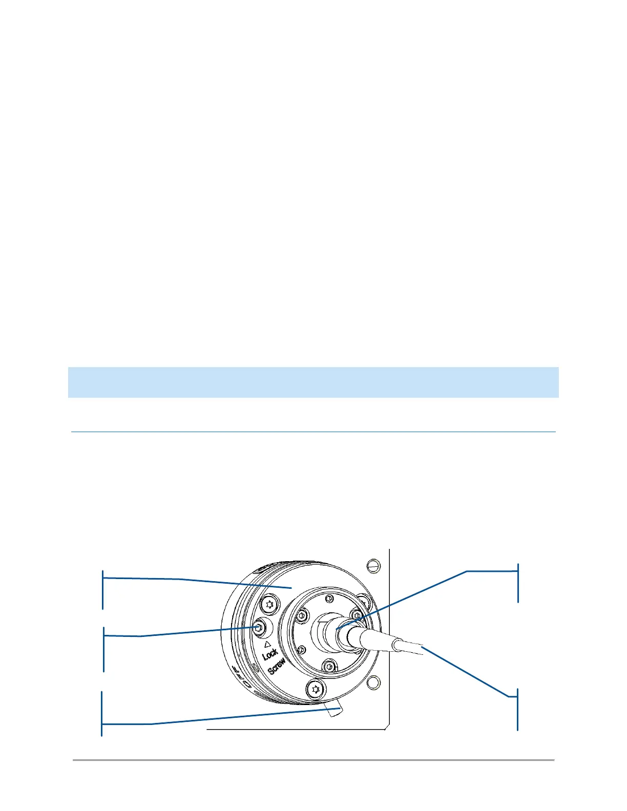
Accessible elements on the repositionable fiber coupling system