25
3-3 Installation
SIGNAL CONNECTIONS
- Connect the remote control to the rear panel of the laser head.
- Connect your remote interlock circuit to the “Interlock” pins on the rear panel of the combiner. If
you are not using an interlock circuit, use the mating connector (provided) to short-circuit these
pins.
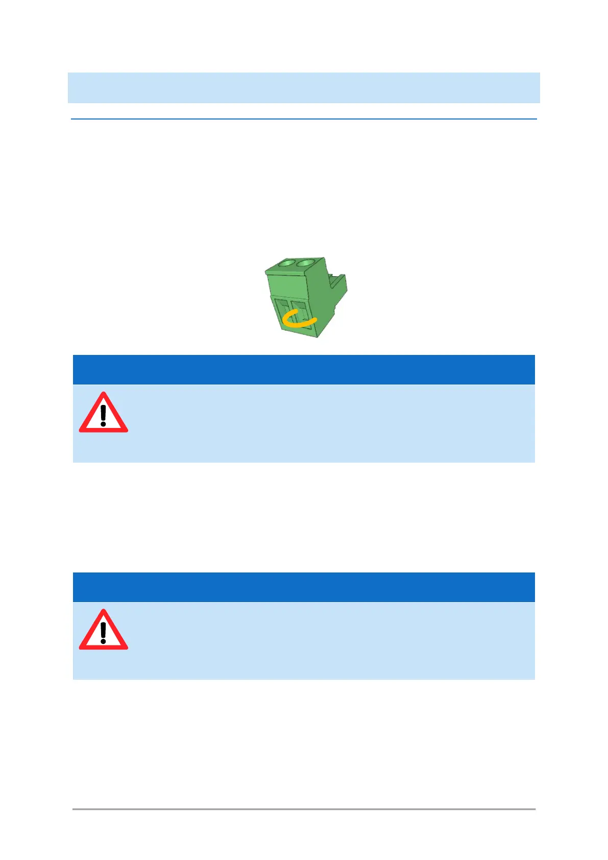
Figure 3-10: Mating connector with shunt wire
- Shutter arming: the I/O port features a specific safety function named the shutter arming circuit,
which overrides the other shutter commands. Apply 5V on pins 11 and 12 in order to arm the shutters
and allow for their control. Applying 0V to these pins, or leaving them disconnected, will prevent the
shutters from opening. Refer to table 4-1 for detailed information about the I/O port.
Alternatively, the DB-25 mating connector (provided) can be plugged in order to shunt these pins and
keep the shutters armed.
- Analog and digital modulation signals, blanking signal: connect your own sources of signals to each of
the input sockets. Refer to the test report of the combiner to understand the assignment between
the laser sources and their modulation ports.
o Voltage range: 0 to +5 Volts
o Impedance: 500 Ohms
Using a shunt wire inside the mating connector will defeat the interlock circuit. As a
result, the user will no longer be able to use this interlock circuit as a safeguard against
accidental exposure to the laser beam.
Using this mating connector will defeat the shutter arming circuit. As a result, the user
will no longer be able to use this function as a safeguard against accidental exposure to
the laser beam.