23
4. I/O port: 25-pin DSub socket used to access to miscellaneous input and output functions of the
combiner by applying appropriate electrical signals. The connecting cable can be a non-shielded
cable, but with a length not exceeding 3 meters. Refer to chapter 3.3, “How to configure the
combiner” for a detailed description of the accessible functions.
5. Supply voltage socket: Input socket for the power supply.
6. Analog input sockets: These inputs are used to control the optical power by applying an analog
voltage. Refer to section 4, “Advanced operation” for detailed information, and to the product
specifications of each source concerning the modulation characteristics. The L4Cc model has four
sockets, while the L6Cc model has six of them.
7. Digital input sockets: These inputs are used to modulate the optical power on and off by applying a
digital signal (0V or 5V). Refer to section 4, “Advanced operation” for detailed information, and to
the product specifications of each source concerning the modulation characteristics. The L4Cc model
has four sockets, while the L6Cc model has six of them.
8. Blanking: This is used to activate the blanking function, shutting down all the laser sources at once.
9. This is the main switch to power on the combiner
10. This label specifies the model, serial number, manufacturing date and supply voltage of the unit.
11. Remote: 15-pin DSub socket to connect the remote control to this socket.
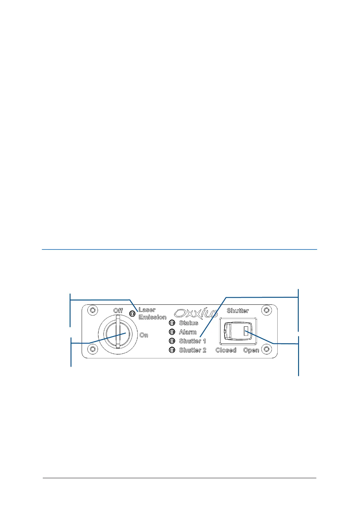
REMOTE CONTROL
The remote control is meant to bring the most essential control elements closer to the user.
Figure 3-8: Front panel of remote control
- Actuated key master control: Also referred as the “Emission key”. A class 3B or class 4 laser
system must incorporate a key-operated control. The key is removable and laser radiation is not
accessible when the key is removed. When the unit is ready, turning the key on will start the
laser emission.
- Laser emission indicator: This indicator is a light-emitting diode (LED) which lights in solid white
when the key control is switched on, indicating that the emission is enabled. It is located on the
remote control so that it can be seen without requiring the user to face the laser radiation, and
its white color is meant to be visible through most protective eyewear. In accordance with CDRH