22
o Optical shutter: When activated, this device is used to prevent any light from being
released out from the output channel. It is driven by either electrical signals or software
commands
o Fiber coupling system (option): This system is designed to release the optical output
into a delivery fiber. It is composed of:
▪ The coupler, which focusses the laser beams into the optical fiber
▪ The optical connector, used to lock the optical fiber in position into the fiber
coupler
▪ The optical patch cable: this removable component holds and protects the
delivery fiber.
- Rear and front angle brackets: the combiner can be fixed to a supporting base using these
brackets.
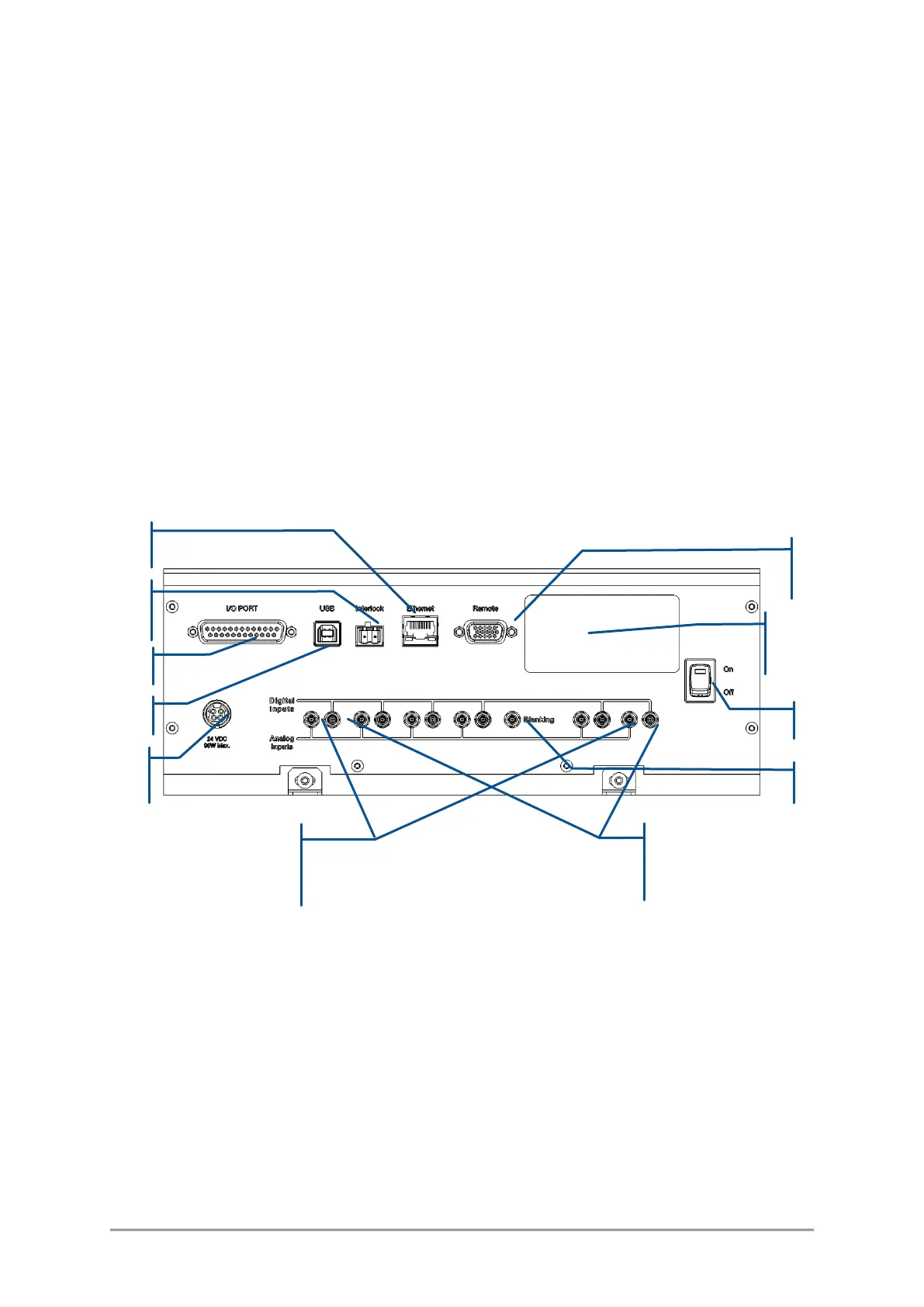
Figure 3-7: Rear panel of the L6Cc combiner
The following elements are accessible from the rear panel:
1. Ethernet: 8-pin, RJ-45 socket to connect the combiner to a Local Area Network (LAN), based on
either 10 or 100BASE-T Ethernet. The linking cable must be shorter than 100 meters. The use of a
category 5 cable is recommended.
2. Interlock: 2-pin socket used to connect the combiner to your own remote interlock circuit. Refer to
section 1, “Safety information”, for more information concerning the remote interlock.
3. USB 2.0 type A interface to control or monitor the combiner using a personal computer. The required
cable is a standard “USB A to B” cable, with a length not exceeding 3 meters. Refer to the following
chapter for the procedure detailing the software installation on a host computer.