57
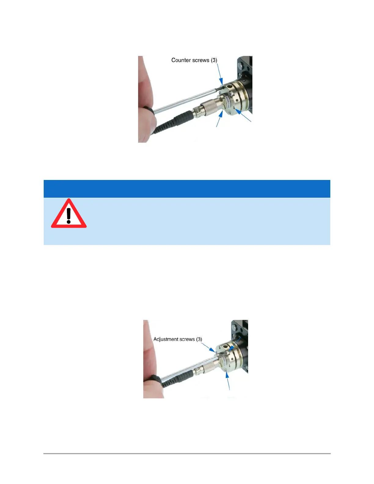
Figure 5-4: Position of the counter-screws
Procedure:
- Power up the laser, set the optical output to a value below 50mW and turn the emission on;
- Set your power meter to its smallest power range (so it can detect even small differences in optical
power) and attach it to the fiber’s end. Locate the adjustment screws (1.5 mm hex cylindrical head,
see Figure 4-5) and turn them one by one (with an Allen 50HD-15 wrench) until the power meter’s
reading indicates that optical power has been detected. A good adjustment sequence should be so
that any possible position is scanned once.
Figure 5-5: Position of the adjustements screws
It is sometimes useful to slightly loosen the nut on the fiber connector, then to pull back slightly the fiber
connector (after having loosen the ferule screw, then the connector nut). Thus doing, defocussing occurrs so
that the spot is easier to find. Fasten the box nut again when you have detected optical power.
The laser is now emitting. Proper protection measures against laser light shall be
enforced
To avoid damaging the fiber end face, the following adjustment procedure should be
performed at low optical power (50mW or below)