Section 300-Installation Chapter 5. Peripheral Equipment
DBS-2.3/9.2-300 DBS Manual - Revised April 2000 5-15
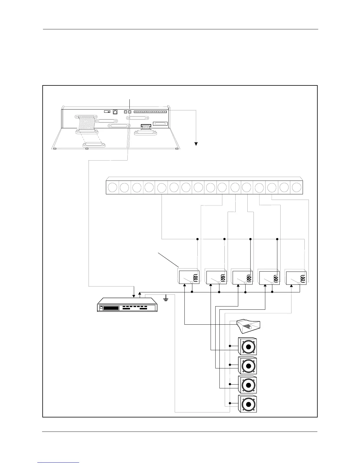
3. Connect the zone relays to the amplifier.
4. Connect the zone relays to the +24V and zone paging terminals (Z0-Z4)
on the Connector Panel.
Figure 5-7. External zone paging installation
Am plifier
All-Page
Speaker
Zone Page
#01
Zone Page
#02
Zone Page
#04
Zone Page
#03
SG
RG
SYN
RG +24V Z0GND C Z2BM Z1 Z3 RE2Z4 RE1-48V
CN4
(R C A C onnector)
CN2
CN11
CN12
CN5
CN13
CN3
CN14
CN15
CN1
CN1
CN2
CN4
6
AudioInput AudioOutput
GND
6
6
6
6
3
3
3
3
3
1
1
1
1
12
12
1212
12
#00
#04
#03
#02
#01
Zone Relay:
UseArom atRelay
Type D F2E-24V
(availableasStock
# 46F5752 at
NewarkElectronics
1-800-4-NEW ARK)
orSimilarRelay
COMMON
MAKE
PAGEALL(ZONE0)
ZONE1
ZONE2
ZONE3
ZONE4
BREAK
Note: This is a simplified example
to show how the connections
operate. A more elaborate paging
system may be installed to balance
volume levels, etc.