6-24
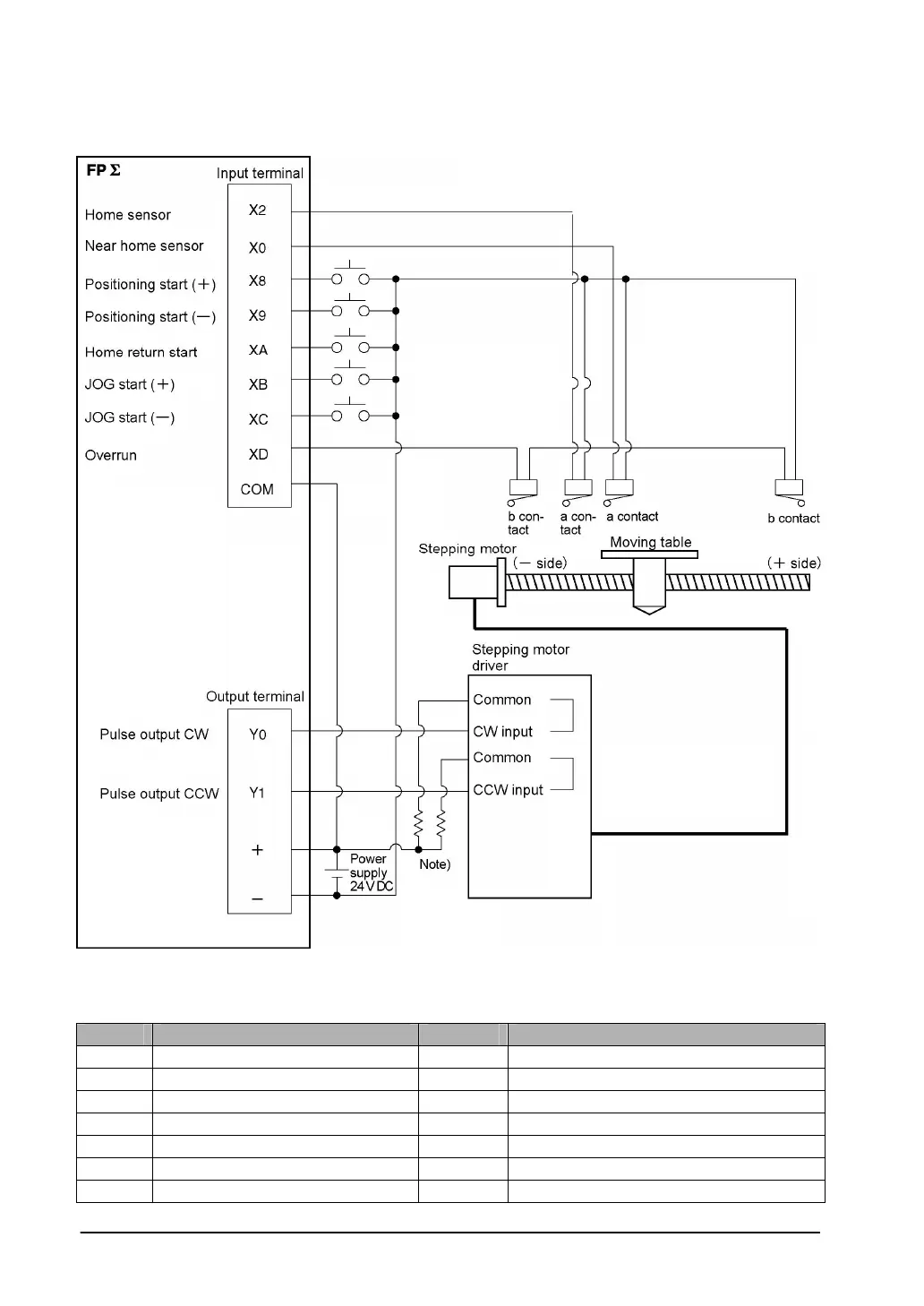
Wiring example
Note) When the stepping motor input is a 5 V optical coupler type, connect a 2 kΩ 1/4 W resister..
Table of I/O allocation
I/O No. Description I/O No. Description
X2 Home sensor input XD Overrunning signal
X0 Near home sensor input Y0 Pulse output CW
X8 Positioning start signal (+) Y1 Pulse output CCW
X9 Positioning start signal (-) R10 Positioning in progress
XA Home return start signal R11 Positioning operation start
XB JOG start signal (+) R12 Positioning done pulse
XC JOG start signal (-) R903A High-speed counter control flag for CH0